|
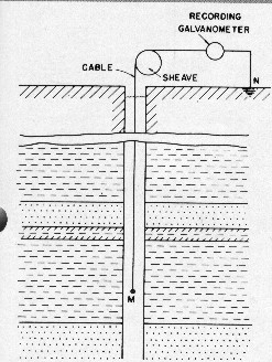
This is a passive measurement. That
is, no energy is provided by the logging tool. There is no
SP until the borehole is drilled and filled with conductive
muds. This contrasts with telluric currents caused by solar
radiation and Northern Lights, and man-made currents from power
lines, cathodic protection of pipelines, and welding equipment
grounded to the rig while logging proceeds. All these currents
can persist without a borehole, but more importantly, can cause
anomalies on the SP log, and in some cases rendering it useless.
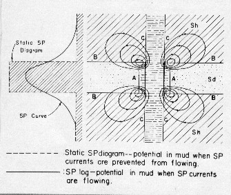
Shales are permeable to sodium ions (Na+) but impervious to chloride ions (Cl-). When a shale separates two sodium chloride solutions of different concentration (the mud in the borehole and the water in the formation), sodium ions migrate by diffusion from the higher concentration into the lower concentration. This movement of positive charges builds up a voltage known as shale potential or membrane potential Em. When two sodium chloride solutions of different concentration are separated by a semi-permeable partition that permits the passage of ions from one side to the other, but prevents bulk mixing of the two solutions, ions migrate by diffusion from the concentrated solution to the dilute solution. This happens at the boundary between the invaded and un-invaded zones. The negative chloride ions have a greater mobility than the positive sodium ions. There is a net transfer of negative electric charges from the more concentrated solution to the less concentrated. The resulting electromotive force is known as the liquid-junction potential Ej. The passage of an electrolyte through a porous medium also produces an electromotive force, called electro-kinetic potential, Ek, between any two points along the electrolyte flow path. For example, an electro-kinetic potential is developed when mud filtrate passes through a mud cake into the formation. The value of this potential is small and is commonly disregarded in electrical logging. The current loops shown below circulate between shale, borehole, invaded zone, and un-invaded zone and back to the shale. They represent the sum of membrane and liquid junction potentials, which is known as the electrochemical component of the SP. The curve to the left is the corresponding SP curve as measured by a real tool. The square static SP is the theoretical shape of a perfect SP curve.
The numerical values of the electromotive forces depend on the type and quantity of dissolved salts. The electrochemical component of the SP is defined mathematically by:
1: Ec = Em + Ej = –K * log(Aw / Amf)
In situations with pure sodium chloride (NaCL) solutions,
the SP equation becomes:
|
|
||
|
Page Views ---- Since 01 Jan 2015
Copyright 2023 by Accessible Petrophysics Ltd. CPH Logo, "CPH", "CPH Gold Member", "CPH Platinum Member", "Crain's Rules", "Meta/Log", "Computer-Ready-Math", "Petro/Fusion Scripts" are Trademarks of the Author |
|||

|
||
| Site Navigation | BASIC PHYSICS SPONTANEOUS POTENTIAL | Quick Links |