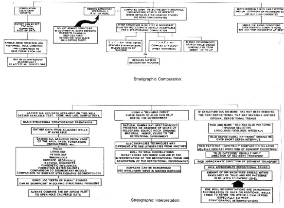
Analysis models of this type are amenable to processing by an expert system, a computer programming style which allows a reasoned dialog to take place between a user and the computer. Such a system was described by Katherine B. Krystinik of USGS, in "An Example Expert System For Computer Interpretation Of Depositional Environments", USGS Open Report #85-30. The responses to previous questions dictate which questions will be asked next by the system. As you can see, the structured question and answer approach is modeled after the thought processes of an experienced sedimentologist. In using the sedimentary models presented below, you should attempt to create a similar logical sequence of questions and conclusions, eliminating as many possible solutions as you can, until only one answer remains.
Additional hints on interpretation techniques are listed in below, taken from Ed Bigelow's masterful paper "Making More Intelligent Use of Dipmeter Data", The Log Analyst, Jan 1985. Examples and quality control methods are also covered in that paper, which is highly recommended reading.
The following sections review each model in detail, and give analysis rules and examples for comparison with your own work. The majority of the examples and some of the descriptive material was taken from "Reservoir Delineation By Wireline Techniques" by J. F. Goetz, W. J. Prins, and J. F. Logan, published in The Log Analyst, June, 1977. Readers interested in more detail than can be presented in this Chapter may wish to study "Sedimentary Environments From Wireline Logs" by Oberto Serra, published by Schlumberger, 1985; a 211 page review of the subject. This book is packed with examples and amplification of the sedimentary models presented here. Some of the following sections were condensed from this reference.
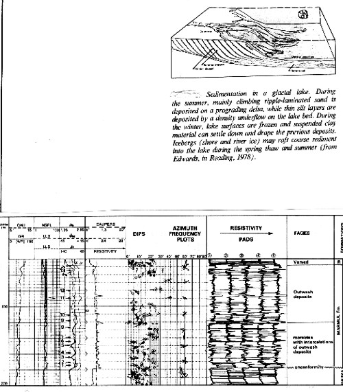
Varves are very thin, roughly horizontal layers deposited in a glacial lake bottom from debris rafted out by the ice. At the edge of the lake, distributary channels deliver sediment to delta type deposits with typical delta front foreset beds. Dipmeter patterns look like delta front distributary mouth bar patterns, but bedding planes are very close together. These occur only behind a receding ice front. Advancing ice will scour away any evidence of the lacustrine delta. A schematic drawing of a glacial lake environment and a typical dipmeter in a glacial environment appear below.
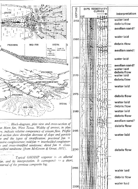
Alluvial fans are long in the down slope direction and very narrow. Thickness varies from a few hundred to several thousand meters. Dip angle is high and scattered. Dip direction is not a good indicator of body geometry. The lower reaches of the fan may grade into a braided stream environment.
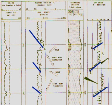
Wind blown dune deposits are often difficult to distinguish from those laid down by water. The mechanics of both processes are quite similar. Although we normally think of dunes as occurring in a desert environment, they often form on beaches and barrier bars, as well as on continental deposits exposed to the air, as in present day Saskatchewan and many parts of North Africa and China. Thus some sediments may go through a wind phase before being finally deposited by water. The dune portion of a barrier bar will be eroded at the top by wave action; this may be repeated many times. Generally, eolian sands are better sorted than aqueous ones, leading to uniformly high porosity and permeability. This makes them excellent reservoirs if they come in contact with source rocks. Some prolific North Sea oil pools are sand dunes. As dunes migrate, sand grains are carried up the windward slope and then roll down the slip face. This results in cross-bedding with enormous set heights. As seen at a borehole, cross-bedding is tabular, high angle, and consistent in magnitude through the height of almost the entire dune. Consistent cross-bedding for intervals of up to 100 feet is common and this distinguishes eolian sands from all others. It is also characteristic that individual dunes, as seen in a borehole, bear no relationship to one another nor to the paleoslope. Wind direction is in the direction of steepest dip and sand body elongation is at right angles to wind direction. Curve shapes are normally cylindrical with funnel shaped bases, the latter being the wadi facies of a dune complex.
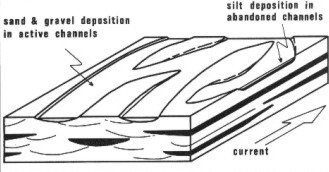
The process is similar to alluvial fan deposition, but occurs on flatter ground and gravity falls of debris are not usual. Braided stream channels cover a large depositional area. They are straighter than meandering streams and rivers, which are formed on flatter terrain.
Braided
stream alluvium is composed of moderately sorted sand and gravel
deposits to the exclusion of silts and clays. When sediments are
well sorted, braided stream deposits show little variation either
vertically or laterally. Both porosity and permeability are high,
forming excellent reservoirs. This textural sequence gives rise
to cylindrical curve shapes when no silt is present and serrated
shapes when silt is present. A fining upward sequence at the top
of each depositional cycle is common. As a result, curve shapes
may show numerous individual patterns which are not correlatable
between wells. This feature is shown schematically below.
Silt is generally deposited in abandoned channels, giving rise to obvious dipmeter channel patterns which are, unfortunately, not very good reservoirs. The shale content indicators show this without difficulty. Water flow during deposition is highly turbulent, resulting in trough or festoon type current bedding. Dipmeter results are erratic in both dip angle and direction because of non-planar bedding surfaces and incomplete depositional sequences. Dip angle varies between zero and 35 degrees while direction may vary up to 180 degrees, but usually remains within a 90 degree arc, which reflects downstream direction and the direction of elongation of the sand body. Planarity rating of dip results are low. GEODIP and SYNDIP presentation assist in recognizing the non-planar beds.
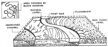
Stratigraphic model and dipmeter in meandering stream environment
At the base is an erosional surface overlain by pebbles and a sequence of sands with an upward decrease in grain size. Coarse festoon cross-bedded sands grade up into tabular cross-bedded sands of diminishing set height. These in turn grade into flat bedded fine sands and then into silts. This sequence gives rise to bell shaped curves. The reservoirs do not take the form of the meander channel but rather that of curved, tabular wedges of sand occupying a large portion of the meander belt. These may be separated from each other by abandoned channel or oxbow lake facies, filled with silt. The meander belt can be up to 20 times the width of the stream. Repeated reworking of the deposits within the meander belt winnows the fine grained material and results in a progressive downstream decrease in grain size. It also results in interrupted sequences and stacking of several of the basal coarse grained parts. Repeated fining upwards patterns (bell shaped) with a coarse grained zone of variable thickness at the base of each cycle is common. Dip magnitude will be erratic and high angled at the base in the festoon bedded sands, progressively becoming more consistent and flatter upwards in the tabular beds. Because of the wide swing in the direction of the depositing currents and the type of current bedding, a variation in dip direction of 180 degrees is normal. The average dip direction should reflect the overall downstream direction of the meander belt and the trend of the separate reservoirs.
Drape over the top of these sand bodies is not usually present. The channel fill itself, however, may drape or sag towards the axis of the valley. The drape within the channel, depicted schematically below, should not be confused with drape ABOVE reefs or bars. Check the curve shape or lithology log to verify that the drape is inside the channel.
Channel cut and fill environment The red patterns still point to the center of the channel, and blue patterns point downstream. Pattern frequency azimuth plots are useful for sorting out these directions. Curve shapes are cylindrical or serrated cylindrical, depending on silt or shale deposition. Bars and channels can be mistaken for each other on logs and cross sections. In the case of a stream channel, the cross section of the sand deposit has it's greatest width at the top and a base that is convex downward. The sand bar has a cross section that is widest at the base, relatively flat at the bottom, and a top that is convex upward. Dipmeter data will usually resolve the two cases. The channel may have drape within the sand body; the bar may have drape above the sand body.
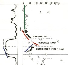
The infilling of a distributary channel is a rapid process and there is no further reworking of the infilling sediments. Current bedding therefore reflects stream energy and direction at the time of deposition. Current bedding near the base is usually of the festoon type. Measured dips are erratic near the base, sometimes grading upward into more consistent dips near the top. The direction of the channel and thus the direction of sand elongation, is given by the average of the current bedding directions. When drape occurs in the channel, the dips point at right angles to the strike. These relatively low angle dips, when observable, are due to channel cutting, and arise from the channel base changing in a series of progressively shallower concave surfaces as infilling proceeds. Unlike braided or meandering stream deposits, which are quite wide due to lateral migration of the channels, distributary channel fills will produce long, narrow reservoirs, often with very thick sections. Distributary channels sit within a delta front sequence (described in the next section), and the channel fill curve shapes will be contiguous with delta front shapes immediately below. The distributary front is characterized by foreset beds (blue patterns) below the base of the channel. A reworked sand may separate the two, defined by random dips. Two examples are shown below.
There
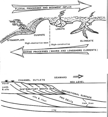
are three main types of deltas: The arcuate delta appears to be the most important as a potential oil trap. Several Pennsylvanian sand fields in Oklahoma are deltaic in origin, as are many of the offshore Gulf Coast fields.
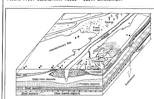
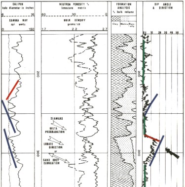
The form developed by a delta depends on the sediment load and the relative strengths of fluvial and marine processes. Where river currents clearly dominate, a highly constructive bird's foot delta, such as the modern Mississippi, will form. These are characterized by elongate bar fingers containing the distributary channels. Where marine processes such as longshore currents are more powerful, a cuspate type delta will develop. An example is the modern Baram delta of Brunei-Sarawak. This type of delta has few distributaries and grows by pro-grading wave generated beaches. A more balanced situation results in a lobate delta form such as the modern Niger. A cross section of a pro-grading delta front in a highly constructive situation is shown in the bottom half of the above illustration. This shows the relative positions and the lithologies of delta front deposits. A highly constructive delta is most favorable to the formation of distributary mouth bars or delta bar fingers. These are sands and silts dropped in front of the mouths of distributary channels which suffer little or no reworking by wave motion. The river currents are the principal factor in determining sand body geometry. Sand bodies usually take the form of elongate or lobate masses extending outward from the river mouth.
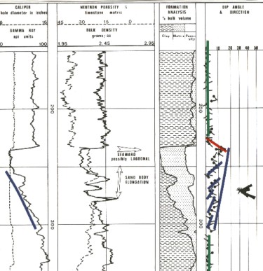
Distributary mouth bar sands are relatively fine grained and moderately sorted. However, curve shapes reflect a general coarsening upward in a highly serrated funnel type configuration. The serrations arise from thin shale layers laid down in times of low water flow. Current bedding is normally tabular and dips in the seaward direction, perpendicular to the strand line, unless deflected by longshore currents. The current bedding dips in the direction of sand elongation. The cross-bedding angle is steepest at the top of the sand unit and decreases downward (a blue pattern). Individual sand units are normally relatively thin. It is not uncommon to have a distributary channel cutting through the top of a distributary mouth bar (a red pattern on top of a blue pattern).
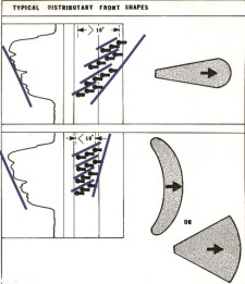
Distributary fronts vary in shape and size due to differences in transport speed and volume, and the interference of the ocean. Long narrow fronts, as may be found in a bird's foot delta, have a relatively high spread in the dip angles of the foreset beds, usually greater than 10 degrees. More compact or fan shaped fronts have dips in their foreset beds of less than 10 degrees.
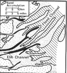
Narrow estuaries develop elongate sand bodies with characteristics similar to those of distributary channel fills except that cross-bedding may be bimodal, that is, cross-beds dip both toward and away from the sea in alternating layers. On the other hand, very wide estuaries create tidal flats which contain some sand, but are often predominately mud. Deposits formed in wide tidal estuaries tend to be a grouping of roughly parallel elongate sand bars amid silts and muds. In cross section, the profile shows coarse sands at the base, grading erratically upwards into shales, with a serrated bell curve shape.
Sedimentary model and dipmeter in tidal flat environment If sediment flow is sufficient, tidal ridges are formed, parallel to the direction of flow. These have coarse grained tops, and generally coarsening upward or cylindrical patterns. Sand body elongation in both cases is in the direction of the tidal currents, indicated by the predominate dip direction in the sand.
Each sand is a separate reservoir, and several producing trends may develop. Such trends can extend for many miles with production confined to the regional noses or highs. The Cotton Valley sands in north Louisiana produce along a trend of over 100 miles. Where drilling is sparse, it may appear that the different beach sands are all the same sandstone body. After sufficient drilling, these apparently blanket sands usually break up into their respective components. Drilling and production decisions will be drastically altered if multiple sands are mistakenly identified as a single sand. Current bedding reflects the wave action showing gentle, tabular, unimodal cross-bedding, with lower angle dips at the base and steeper at the top of the sand. The direction of cross-bedding is seaward, normal to the direction of elongation of the sand body. Beaches cannot be distinguished easily from distributary mouth bars by dipmeter data. Stacking of several beaches is common and both regressive (funnel shaped), transgressive (bell shaped), and cylindrical curve shapes are possible. In rare cases, overlying shales may show some draping dip. This dip points in the direction of seaward pinchout, but in practice it probably occurs over surfaces which have been cut by erosion, and therefore may not indicate the coastline orientation. As mentioned, beaches generally give rise to long, narrow sand bodies. On the other hand, deltas dominated by longshore currents create beaches which tend to form to the side of, and between, distributary mouths. As the delta progrades, sheet sands are formed with regressive characteristics and low angle, tabular cross-bedding. These are sometimes broadly classified as delta front sands. Log curve shapes and dip data cannot distinguish between these sheet sands and narrow beach sands.
Basal unconformity sands have stronger cross-bedding angles, proportional to the topographic relief. In addition, there is usually draping dip due to differential compaction in the overlying beds. Draping dips point away from the local high on the erosional surface. Granite wash sands typically exhibit this behavior. These sands are composed of granite fragments, feldspar, quartz, and silt. They do not have very good curve shapes due to the radioactive elements affecting the gamma ray log and the impermeable granite affecting the SP. The density log curve shape or a well computed lithology log using natural gamma ray spectral and photoelectric data may do the job.
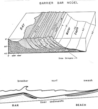
With
an adequate supply of sediment, a bar becomes emergent, forming
a barrier. Barrier bars have gentle dips on both sides and are
often associated with coal swamps or evaporitic lagoons on the
landward side. The barrier bar is formed by regression of the
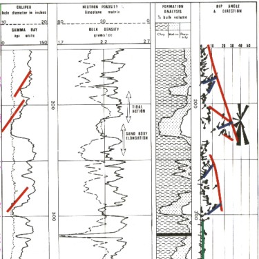
shoreline, and contains three fundamental units: These units can usually be identified on logs by the coarsening upward (funnel) curve shape. If sequence is surrounded by shales, the shale may undergo more compaction than the sandstone of the barrier bar. This differential compaction, or drape, over the sand bar is noticeable on dipmeter data or on well to well correlations, and is a strong clue to following the bar for future drilling.
There is no good standard type section for marine shelf sands. The shelf sands themselves usually have a rounded base and rounded top on the gamma ray or SP log, but stacking of these sands, and reworking of the top into bars makes the patterns difficult to spot. Erratic dips at the top surface due to ripples, scouring, and animal burrows or tracks may be visible. Sorting may vary from good to poor. Curve shapes, on the average, will exhibit a serrated combination funnel-bell appearance. Current bedding is low angle and polymodal or random.
These true blanket sands should not be confused with beaches and bars (which are sometimes called blanket sands), as their curve shapes and dipmeter patterns are very different, not to mention the reservoir extent and quality.
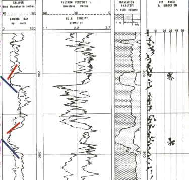
Dipmeter in marine shelf (blanket carbonate) environment
Bell and cylindrical curve shapes usually correlate to red patterns, and bell shaped to blue patterns. However the shapes are not taken from the usual gamma ray and SP logs. They are taken instead from the dipmeter microresistivity curves. Any one of the 4 or 8 curves, or the resistivity correlation curve, will do.
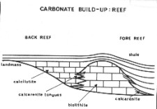
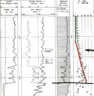
Present day reefs occur mainly in shallow tropical seas. Reef growth requires sunlight (clear water, shallow depth), oxygen (rough water), food supply, and a favorable temperature. Fringing reefs are linear and stretch parallel to the coast with no intervening lagoon. Barrier reefs are similar but a lagoon separates them from the land. Atolls are subcircular reefs enclosing a lagoon often built around a sinking volcano. The seaward or fore reef edge of a reef is normally quite steep and may form a talus slope of reef detritus at its base. Cross-bedding dips pointing away from the immediate reef high can be measured in this detrital wedge. The back reef, or quiet lagoonal side of the reef, is made up of very fine grained material, interbedded with calcareous mud and may show relatively flat beds or no bedding at all on the dipmeter.
After reef organisms are killed due to some change in conditions, the reef mass may be buried in mud. Overburden weight causes compaction in the muds leading to sizeable draping dips. Compaction may be as great as 50%, generating draping dips as high as 30 degrees. Draping dips point down, away from the reef buildup.
A rule-of-thumb has been established to determine the reef shape. In the first case, compaction contemporaneous with deposition is characterized by low resistivity shales exhibiting a gradual buildup of dip versus depth. Here, reef front angle equals maximum draping dip plus 10 degrees. If compaction is mainly after deposition, characterized by a fairly constant draping dip in the overlying shale, then reef front angle is about twice the maximum draping dip. In some areas of the world, such as northern Alberta, salt solution around the reef accentuates drape, and the above rules do not apply. Reef porosity is extremely variable and follows no particular pattern versus depth. The biolithic zones, or reef core, will normally be the most porous. All three usual rock types, biolithite, calcarenite (fore reef), and calcilutite (back reef) may develop porosity in the form of vugs, fractures, and dolomitization. Porosity curve shapes are therefore not very predictable, but the gamma ray will be cylindrical. The SP usually will not have a meaningful shape due to the effect of nearby impermeable carbonates. The percentage of dolomite can be determined by porosity log crossplots and calcarenite (limestone matrix) can be distinguished from calcilutite (quartz/chert matrix) in the same manner.
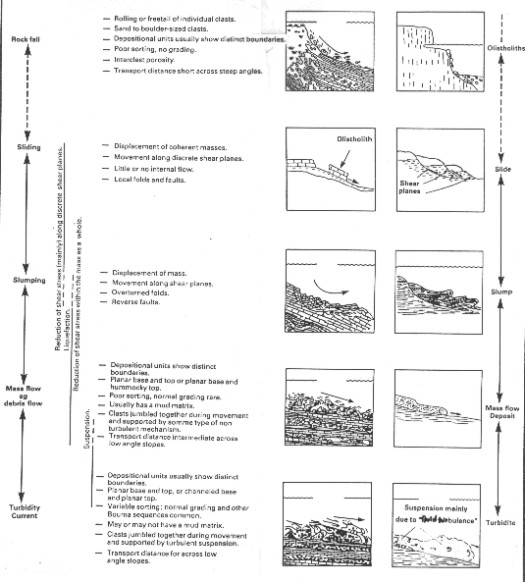
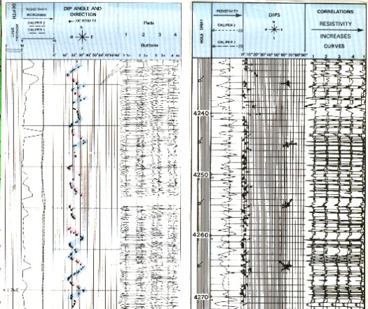
Turbidite deposits can be tabular, elongate, or fan shaped. Individual sand beds are poorly sorted, but the upward fining of grain size produces roughly bell shaped log curves for each cycle of deposition. Rhythmic alternation of graded beds with shales produces a stacking of numerous similar curve shapes. A characteristic of turbidites, in spite of being a high energy deposit, is the absence of appreciable cross-bedding. Dipmeter results will therefore show little variation from structural dip, and will not be very helpful in defining sand body geometry. Below are LOC DIP results for a sand turbidite sequence and another from a carbonate turbidite.
Turbidites
deposited in deep marine basins may be interbedded with muds which
can be hydrocarbon source rocks. However turbidite sands do not
generally make good reservoirs because poor sorting and clay matrix
inhibit porosity and permeability. The thin bedding of turbidite
sands and the intervening shales make reservoirs numerous, but
thin and disconnected. |
|
|||||||
|
Page Views ---- Since 01 Jan 2015
Copyright 2023 by Accessible Petrophysics Ltd. CPH Logo, "CPH", "CPH Gold Member", "CPH Platinum Member", "Crain's Rules", "Meta/Log", "Computer-Ready-Math", "Petro/Fusion Scripts" are Trademarks of the Author |
||||||||

|
||
| Site Navigation | STRATIGRAPHY DIP PATTERNS IN STRATIGRAPHIC SEQUENCES | Quick Links |
 Stratigraphic model for braided stream environment
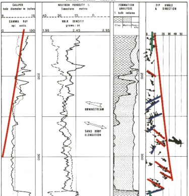
 Point
bars are formed in the inside of bends in rivers and streams,
where the current slows. down and drops out some of its sediment
load These bars are small, and difficult to find
due to the meandering nature of the original river. They are attractive
exploration targets because their reservoir characteristics are
usually good.
Point
bars are formed in the inside of bends in rivers and streams,
where the current slows. down and drops out some of its sediment
load These bars are small, and difficult to find
due to the meandering nature of the original river. They are attractive
exploration targets because their reservoir characteristics are
usually good. 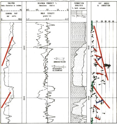 The
Mississippi River is a modern example of such a stream. Point
bar deposits are also called lateral accretion deposits.
The
Mississippi River is a modern example of such a stream. Point
bar deposits are also called lateral accretion deposits.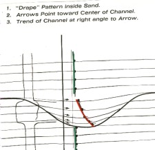
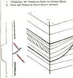 Foreset
beds within the channel, shown at left, mask the drape
effect.
Foreset
beds within the channel, shown at left, mask the drape
effect.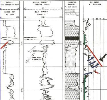 By
blockage of the mouth or shifting of the stream above, stream
velocity may drop and deposition will occur. The depositing material
is coarse grained and well sorted. Normally more coarse material
is found at the base and there is a general fining upward. However,
in many cases, the entire channel becomes clogged with uniform
sands. These give rise to characteristic cylindrical curve shapes,
possibly grading into bell shaped at the top.
By
blockage of the mouth or shifting of the stream above, stream
velocity may drop and deposition will occur. The depositing material
is coarse grained and well sorted. Normally more coarse material
is found at the base and there is a general fining upward. However,
in many cases, the entire channel becomes clogged with uniform
sands. These give rise to characteristic cylindrical curve shapes,
possibly grading into bell shaped at the top. 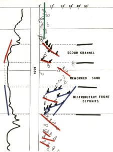
 Dipmeter in distributary mouth bar environment
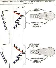
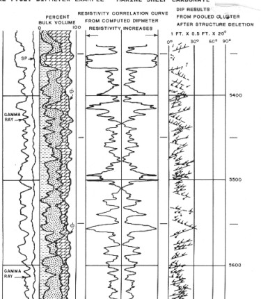 In
subtidal marine carbonate detrital sections, detailed dipmeter
analysis is fruitful if the data is of good quality. Usually the
GEODIP program is necessary. Red and blue patterns have their
usual relationships to transgressive and regressive behavior,
but they will often be very short patterns due to the slow depositional
process this far offshore. Dip direction is unimodal, in the deepening
(usually thinning) direction. Direction of elongation is perpendicular
to dip direction.
In
subtidal marine carbonate detrital sections, detailed dipmeter
analysis is fruitful if the data is of good quality. Usually the
GEODIP program is necessary. Red and blue patterns have their
usual relationships to transgressive and regressive behavior,
but they will often be very short patterns due to the slow depositional
process this far offshore. Dip direction is unimodal, in the deepening
(usually thinning) direction. Direction of elongation is perpendicular
to dip direction.