|
 PERMEABILITY BASICS
Most quantitative petrophysical log analysis is aimed
at defining shale
content, porosity,
and water saturation. These terms define the oil or gas in
place in the reservoir at initial conditions. What we would
really like to know is: "Is the well any good?" That is,
will it produce anything, and if so, how much per day. To
know this, we must determine values for permeability and
productivity.
Permeability,
also known as hydraulic conductivity,
refers to the ease with which fluids flow through any substance.
It is not sufficient to have oil or gas in a formation; the hydrocarbons
must be able to flow from the reservoir into the well bore in
order to be recovered at the surface. Absolute permeability is
a physical characteristic of the rock. Permeability of a rock
for oil, gas, or water is a function of the absolute permeability
and the viscosity of the fluid.
Productivity
describes the flow rate of oil or gas into the well bore. These
two terms are obviously related. This Chapter explains how to
determine these values from open hole log data.
Reservoir
volume is a term used, with other adjectives, to describe the
volume of hydrocarbon in the reservoir. It is also called the
oil in place or gas in place. The phrases, reserves or recoverable
reserves, refer to the amount of hydrocarbon in place that can
actually be produced under the existing (or a proposed) recovery
mechanism.
Recoverable
reserves and productivity define, along with product prices and
production costs, whether or not a well will make money; that
is, "Is the well any good?"
Permeability
is measured by flowing fluids through the rock under known conditions.
This can be done on rock samples in the laboratory, or by flowing
a well (in -situ measurement). It depends on the size and shape
of the pores and pore throats, the properties of the fluids, the pressure exerted
on the fluid, and the amount of the fluid flow.
 Darcy's fluid flow equation Darcy's fluid flow equation
Darcy's fluid
flow equation relates these properties to permeability.
For
linear horizontal flow:
1: Q = 1.127 * A * (K / MU) * (P1 - P2) / L
Where:
Q = quantity of fluid (bbl/day)
A = area fluid flows through (sq feet)
K = permeability (Darcies)
MU = viscosity of fluid (centipoise)
P1 - P2 = pressure differential (psi)
L = length of flow path (feet)
For
non-horizontal flow (eg. up-dip in a reservoir) a gravity term
must be included.
More
importantly, fluid flow from a reservoir into a wellbore is not
linear but radial, so the equation becomes:
2: Q = 3.07 * H * (K / MU) * (Pr - Pb) / log(Rr/Rb)
Where:
Q = quantity of fluid (bbl/day)
H = thickness of reservoir that fluid flows through (feet)
K = permeability (Darcies)
MU = viscosity of fluid (centipoise)
Pr - Pb = pressure differential from reservoir to wellbore(psi)
Rr = radius of reservoir = length of flow path (feet)
Rb = radius of wellbore (feet)
The
unit used in measuring permeability is the Darcy. Permeabilities
normally encountered in reservoir rocks range from less than one
millidarcy in low porosity sandstones, to about fifty Darcies
in fractured rock. In tight gas and shale gas reservoirs,
natural matrix permeability may be as low as a few microdarcies.
Although
there are some general trends of increasing permeability with
increasing porosity, these do not necessarily hold for any given
situation. If the sand grains are large, then the pore throat
diameters are large and the permeability is high. If the size
of the sand grains is reduced by a factor of l00, the permeability
is considerably smaller, but the porosity will be the same. Smaller
pores mean larger surface areas around them, and therefore more
resistance to flow (lower permeability). Various authors have
proposed equations that account for these effects:
Slichner: K = 10.2 * D^2 / CK1
Terzaghi: K = CK2 * D^2 * ((PHIe - 0.13) / (1 - PHIe)^0.33)^2
Uren: K = CK3 * D^2 * PHIe^3.31
Kozeny K = CK4 * PHIe^3 / ((1 - PHIe^2) / (Sv^2)
Kozeny-Carmen K = CK5 * PHIe^2 * Rp^2 * Cpur
Where:
CK1 = 10 to 100 depending on porosity and grain packing
CK2 = constant to be determined by calibration
CK3 = constant to be determined by calibration
CK4 = 0.20
CK5 = 0.04444
Cpur = 0.216
D = average grain diameter (cm)
K = permeability (Darcy)
PHIe = porosity ((fractional)
Rp = pore throat radius (microns)
Sv = specific surface area of grains (sq cm)
Since
D, Sv. and Rp are not easily measured, these are not very practical
equations for use in log analysis. However, they do resemble the
form of practical equations presented later in this Chapter. The
practical equations give permeability as a function of effective
porosity and irreducible water saturation, with some tune-ups
for shale volume or pore geometry.
 PORE THROAT RADIUS
The Kozeny-Carmen
equation can be rearranged to calculate pore throat radius (Rp),
which helps us to understand pore geometry variations within a
reservoir.
1: Rp = (K / (44.44 * PHIe^2))^0.5
Dr Zoltan Barlai has proposed some empirical equations that may
also be useful:
2: Rp = 1 / (C * (Vclay + Vsilt)*D + E)
3: 3: Rp = 1 / (G *
(Vsh / PHIe^2)*H + J)
4: Rp = Rpmax * (1 - Vsh)^2
Where:
C, D, E, G, H, J = regression coefficients
K = absolute permeability (mS)
M = cementation esponent (unitless)
PHIe = effective porosity (fractional)
Rp = pore throat radius (microns)
Rpmax = representative or maximum pore throat radius in a clean sand (micronss)
 Definitions of
permeability
Permeability
measured with only one fluid in the pores is equal to the absolute
permeability, because Darcy's equation accounts for the viscosity
and pressures involved in the measurement process. The
measurement is often made using air as the fluid, but brine is
also used. There is a small correction, called the Klinkenberg
correction, to reduce air permeability to a liquid permeability.
The absolute permeability is abbreviated as K, Ka, or Kair.
Effective permeability refers to permeability
when one fluid flows in the presence of a second fluid in a pore
system, for example oil flowing and irreducible water not
flowing. Effective permeability is less than absolute permeability
because the presence of a second fluid reduces the size of holes
available for flow of the first fluid. If no fluid flows, the
effective permeability of the rock to that fluid is zero.
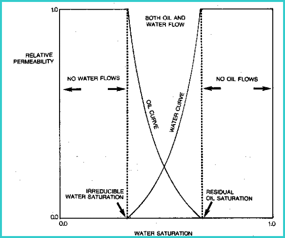
Relative
permeability is the ratio of effective permeability of a specific
fluid to absolute permeability. Graphs of relative permeability
curves reflect the capacity of
the rock to produce fluids by showing the permeability of those
fluids as a function of saturation.

Typical relative permeability curves for oil
and water

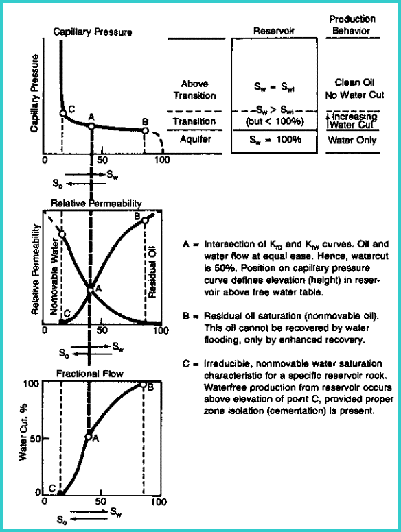
Relative permeability and capillary pressure curve
compared
The
amount of fluid flowing is not a direct result of the relative
permeability, as different fluids have different viscosities.
For example, if gas and oil have equal relative permeabilities,
more gas than oil will flow within the rock because of the dramatic
difference in viscosity.
Most
core analysis reports provide three permeability measurements
labeled Kmax, K90, and Kvert. Kmax is the permeability in the
horizontal direction through the core with the highest permeability.
This direction is determined by measuring the pressure drop across
the core and then rotating the core until the minimum pressure
drop is located. This permeability is sometimes labeled Khor,
Khoriz, or Kh.
After
rotating the core 90 degrees from the direction of Kmax, K90 is
measured. K90 must be less than or equal to Kmax.
Kvert
is then measured by flowing fluid through the vertical direction
on the core. Kvert is often less than Kmax in sandstones and shaly
sandstones. It may be higher than Kmax if semi-vertical fractures
exist, as in many carbonate reservoirs.
The
permeability derived from log analysis is the absolute permeability,
if it is calibrated to the absolute permeability from core data.
Usually, log results are calibrated to the maximum permeability
from core (Kmax). Effective permeability can usually be derived
from absolute permeability, using empirical relationships.
The
irregular, narrow connections between pores are called capillaries.
They can be likened to thin tubes connecting any two points in
the reservoir. Capillary pressure is the phenomenon by which water
or any wetting liquid is drawn up into a vertical capillary. The
smaller the capillary, the higher the liquid rises.
Due
to the variety of capillary diameters, the water saturation within
a rock varies above the hydrocarbon-water contact. The water saturation
caused by capillary pressure in the hydrocarbon zone is called
the irreducible water saturation. A zone at irreducible water
saturation will not produce water. A zone that is very wet AND
at its irreducible water saturation will not flow water. A zone
could have such poor permeability that an apparently wet zone
can occur anywhere in an oil or gas column. This problem is solved
by calling the apparently wet zone "tight", or impermeable",
or "non-pay". It is not a “water zone”.
Between
the water and hydrocarbon zones, is a layer of rock filled with
both water and oil, with the water at a saturation higher than
the irreducible saturation. It is considered the region in which
both water and oil (or gas) will flow. It is termed the transition
zone. This should not be confused with the same term used to describe
the invasion of mud filtrate into the formation.
The
more small capillaries there are, the higher the water saturation
will be. Also the transition from irreducible water saturation
to 100% water throughout the transition zone will be longer. The
fraction of water flowing with the oil (or gas) is referred to
as the water cut.
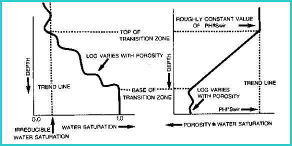
These
definitions suggest that it is important to know the top depth
and base of the transition zone, so that a well can be produced
from above the top of the transition zone to minimize water production.
This may not be obvious from specific values of water saturation,
because the porosity is seldom constant, but it may be more apparent
by observing the porosity times water saturation product (PHIxSW)
through the transition zone. Compare the illustration on the right
side of the illustration below with that on the left.

Identifying transition zone from PHI*SW product
 Permeability of Fractures Permeability of Fractures
The permeability of fractures is a function of the width
(aperature) of the
fracture. A rough relationship, proposed by Dr Zoltan Barlai, for permeability versus width (in imillimeters) of a fracture is:
10: PHIf = 0.001 * Wf * Df * KF1
11: Kfrac = 833 * 10^11 * PHIfrac^3 / (Df^2 * KF1^2)
12: Kfrac = 833 * 10^5 * PHIfrac * Wf^2
13: Kfrac = 833 * 10^2 * Wf^3 * Df * KF1
Where:
KF1 = number of main fracture directions
= 1 for sub-horizontal or sub-vertical
= 2 for orthogonal sub-vertical
= 3 for chaotic or brecciated
PHIfrac = fracture porosity (fractional)
Df = fracture frequency (fractures per meter)
Wf = fracture aperture (millimeters)
Kfrac = fracture permeability (millidarcies)
Note:
Equations 11, 12, and 13 give identical results.
Therefore,
a fracture 1 millimeter thick has a permeability of 83 darcies
(or 83,000 millidarcies).
|

