|
 Calculating Seismic
Wavelets
If a wavelet can be extracted by autocorrelation of a real seismic
trace, it should be used to make the synthetic. If this cannot
be done, wavelets are generated from equations which describe
the frequency content of the wavelet. There are two types - Ricker
wavelets are generated directly in the time domain and Klauder
wavelets are generated in the frequency domain. Both are called
zero phase wavelets and are a minimum delay. That is, the maximum
energy is at the beginning of the wavelet. Ricker wavelets are
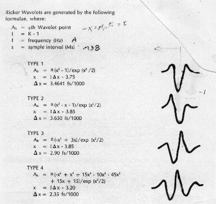
shown below.

Standard computed wavelet shapes
There
are four different Ricker wavelets, called Ricker Type 1, Type
2, Type 3, and Type 4 respectively. The higher types have more
peaks and valleys, representing more "ringing", and
are less symmetrical.
Ricker wavelets are used when
the synthetic seismogram is to match dynamite or airgun data.
They are computed from the following:
 Ricker
Type 1:
1: G = 3.4641 * CFREQ / 1000
2: FOR I = 1 TO WVLTLENGTH / SAMPRATE
3: X = (I * SAMPRATE - 1) * G - 3.75
4: Wvlt [I] = (X * X - 1) / EXP (X * X / 2)
5: NEXT I
 Ricker
Type 2:
1: G = 3.65 * CFREQ / 1000
2: FOR I = 1 TO WVLTLENGTH / SAMPRATE
3: X = (I * SAMPRATE - 1) * G - 3.85
4: Wvlt [I] = (X * X - X - 1) / EXP (X * X / 2)
5: NEXT I
 Ricker
Type 3:
1: G = 2.9 * CFREQ / 1000
2: FOR I = 1 TO WVLTLENGTH / SAMPRATE
3: X = (I * SAMPRATE - 1) * G - 3.85
4: Wvlt [I] = (-X^3 + 3 * X) / EXP (X * X / 2)
5: NEXT I
 Ricker
Type 4:
1: G = 2.35 * CFREQ / 1000
2: FOR I = 1 TO WVLTLENGTH / SAMPRATE
3: X = (I * SAMPRATE - 1) * G - 3.2
4: Wvlt [I] = 0.1*(-X^6+X^5+15*X^4-10*X^3-45*X*X+15*X+15)/EXP(X*X/2)
5: NEXT I
When
comparing synthetic seismograms with different wavelets, it is
important that each wavelet have the same initial energy. The
energy can be found by squaring and summing each of the Wvlt[I]
terms. The sum is then compared to a standard energy of 1.0 and
a scale factor derived, which is multiplied against each Wvlt[I]
term to obtain normalized wavelet values.
The
Klauder wavelet is generated in the frequency domain, which gives
the amplitude and phase spectra of the wavelet. The autocorrelation
of the spectra produces the wavelet shape in the time domain.
This wavelet is used when the synthetic is to match Vibroseis
data.
 Klauder
Wavelet:
STEP
1: Generate chirp signal amplitude and phase
1: CFREQ = 0.5 * (LFREQ + HFREQ)
2: KLFREQ = (HFREQ - LFREQ) / SWEEPLENGTH
3: K = SAMPRATE / 1000
4: FOR I = 1 TO SWEEPLENGTH / K
Calculate
phase
5: I[I] = 2 * PI * (LFREQ * I * K + KLFREQ * I * I * K * K / 2)
+ INITPHASE
Calculate
amplitude
6: R[I] = 1250 * COS(I[I])
Put
phase in all 4 quadrants
7: I[I] = TAN (I[I])
8: I[I] = ATN (I[I])
9: I[I] = I[I] * 180 / PI + 180 * (SIN (I[I]) < 0) + 90
10: NEXT I
STEP
2: Calculate autocorrelation to get wavelet in time domain. This
double nested loop takes the first 100 data points and cross correlates
them with the last 100 data points of the sweep. Since the number
of data points is small, there is little advantage to using the
FFT for the correlation.
1: I = SWEEPLENGTH / SAMPRATE - 1
2: K = 1
3: FOR J = SWEEPLENGTH/SAMPRATE TO SWEEPLENGTH/SAMPRATE - 100
BY -1
4: Auto[K] = 0
5: FOR L = 1 TO J
6: Auto[K] = R[L] * R[I - J + L] + Auto[K]
7: NEXT L
8: K = K + 1
9: NEXT J
To
see the wavelet shape, the correlation string is reversed and
paired with itself:
10: FOR I = 1 to 100
11: Wvlt[I] = Auto[100 - I + 1]
12: NEXT I
13: FOR I = 101 TO 199
14: Wvlt[I] = Auto[I - 99]
15: NEXT I
|

