|
 WIRELINE LOGGING BASICS
To perform a logging operation
on wireline, the measuring instrument, often called a probe, sonde
or logging tool, is lowered into the borehole on the end of an insulated electrical
cable. The cable provides power to the downhole equipment. Additional wires
in the cable carry the recorded measurement back to the surface. The cable
itself is used as the depth measuring device, so that properties measured
by the tools can be related to particular depths in the borehole.
Wireline logs descend into the wellbore under
the force of gravity. In deviated wells, the tools may not travel
all the way to bottom. Roller and powered tractor subassemblies can
be used to assist. These are not especially useful in rough or
horizontal wells, so coiled tubing or pipe conveyed tools are used.
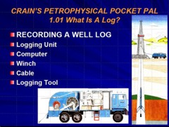
  The
wireline logging operation showing logging truck (right),
logging cable strung into the rig, then lowered into the
borehole (left), with logging tools at the end of the cable
(bottom). Logs are usually recorded while being pulled
upward by the winch in the logging truck. Most logs can also be
run as an integral part of the drill string (logging while
drilling or LWD) or attached to coiled tubing. These methods are
useful in deviated, horizontal, or other hostile well
environments. The
wireline logging operation showing logging truck (right),
logging cable strung into the rig, then lowered into the
borehole (left), with logging tools at the end of the cable
(bottom). Logs are usually recorded while being pulled
upward by the winch in the logging truck. Most logs can also be
run as an integral part of the drill string (logging while
drilling or LWD) or attached to coiled tubing. These methods are
useful in deviated, horizontal, or other hostile well
environments.
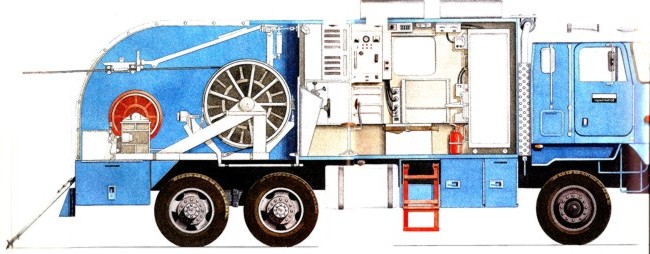
Cutaway view of a modern logging
truck showing winch with logging cable (left) and computerized
operator's station (center)
A
logging tool is made up of a sonde and a cartridge. The sonde
is the portion of the tool which gives off energy, receives energy,
or both. The cartridge contains the electrical circuitry or computer
components needed to control the downhole equipment, and to transmit
data to and from the surface.
Combination
logging tools consist of more than one sonde and cartridge, so
that more than one log can be recorded on a single trip into the
wellbore.
Surface
equipment is mounted in a logging truck, van, or skid unit from
which all logging operations are controlled. The logging unit
contains hoisting equipment for lowering and raising the tools
in the hole, and electronic or computer equipment for controlling
and recording the downhole measurements.
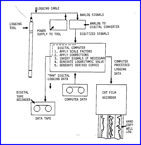
Recording the well log involves a number of steps, beginning
with sensing and pre-processing the measurement in the logging
tool itself, transmission of this information to the surface
over several miles of wireline, further processing in the
logging truck computer, data storage on disc or magnetic tape,
and finally display of the data on film or paper.
Measurements are recorded in two forms, analog and
digital. The analog data may be recorded on photographic film,
electronic plotter, or chart recorder. The same data are captured
in digital form on magnetic tape or disc for later use in computer
aided petrophysical analysis. Many instrument control and calibration functions
are now handled by the same computer used to record the digital
data, with some human control. The result is a log, as seen
below.
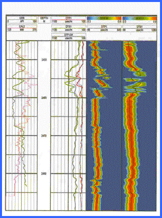
Example of a Well Log, with a standard 3-track
presentation on the left and an image log on
the right. Curve
names and scales in the scale heading help identify which
curve is which.
All logging tools and surface equipment must be properly
calibrated. Service companies have calibration procedures for
most tools, some of which are based on standards established
by the American Petroleum Institute (API). Each tool must be
calibrated at the surface before placing it in the hole to
make measurements, and must pass certain calibrations after
the measurements are complete to verify that measurement accuracy
has not drifted. Some tools also have downhole calibration
checks.
After reaching total depth, or some other location
of interest in the borehole, measurements are made while pulling
the tool upward over several hundred feet of the borehole.
This is called the repeat run, and is used to determine the
repeatability of the measurements when compared to the main
logging pass. After the repeat run is complete, the tool is
lowered to the bottom of the hole, and the main logging pass
is commenced. During the early portion of these measurements,
the responses are compared to those of the repeat run to determine
that no instrument drift has occurred. Results of all field
calibrations and repeats are attached to the bottom of the
well log record.
In addition to the actual measurements, the well log
itself contains information about the logging process which
supports use and interpretation of the data. The well name,
location, date, surface measurements on the mud system, drill
bit size, casing information, and logging equipment data are
found on the log heading, Any pertinent information or comments
regarding the logging job may be recorded in the remarks section.
The logging equipment is carried to the wellsite on
a truck (for land based operations near roads), or transported
by helicopter on skids (for remote land operations) or are
permanently mounted on offshore rigs. Some typical logging
units are shown below.
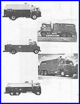
Logging Trucks and Skid Units
Computerized surface equipment is now the rule rather
than the exception. Such units, on a truck and with logging
tools on board, can cost over $1,000,000.
|