|
 WIRELINE DEPTH DETERMINATION BASICS
Depth is the singular measurement that ties together all other
measurements made in a wellbore. Integration of all the
petrophysical measurements at a particular depth allows us to
evaluate reservoir properties. Well completion, stimulation, and
remedial workover activities can then be related to these depths.
The most commonly used depth measurement is that from wireline
logging operations. Driller’s depth and cuttings sample depths may
also be used, but the latter can be quite inaccurate. Wireline
depths can be calibrated for line stretch and temperature expansion.
Driller’s depth is determined by measuring the length of each drill
pipe length that is run into the hole. Added to this is the length
of the bottom hole assembly (BHA) and the position of the travelling
block that carries the pipe in and out of the hole. The respective
lengths are measured with a steel tape measure and recorded on a form
or in a computer program. Pipe stretch and thermal expansion
corrections may be applied in deep, hot boreholes.
Sample depths are estimated based on mud circulation rate and
checked by measuring the time taken to circulate a recognizable
chemical from surface and back again. Sample depths are then refined
by noting drilling rate variations with the lithology of the
samples.
For wireline depth determination, the wireline logging cable is the
“tape measure”. It is “read” by a device called a “measuring wheel”
that rides on the cable and creates depth indicating pulses as the
cable moves up or down in the wellbore. The logging tool
measurements are made and recorded at some fixed depth increment,
for example 6 inches (0.1524 meters) or 0.100 meters. High
resolution data can be recorded at 10 or 20 times the standard
sample rate. The output from this depth measurement is called Raw
Depth.
Magnetic marks are usually placed on the wireline cable under
constant tension at the service company field location. These are
usually spaced every 100 feet and are used to help calibrate the Raw
Depths that come from the measuring wheel pulses. The result is
called Calibrated Depth.
Calibrated depth corrected for elastic cable stretch, temperature,
and tension regime is called Corrected Depth and represents the
best estimate of the depth in a wellbore.
True Along Hole depth (TAH) is the true and correct position in a
well bore, determined by the length along the center of the drilled
hole from a surface reference point (e.g. rotary table, kelly
bushing, wellhead casing flange) to a measurement point, typically a
measuring point of the logging tool.
Loggers, or wireline, (WL) Depth is the depth measured by the
logging service provider and provided as either “Raw”, “Calibrated”
or “Corrected” depth, as defined above.
Indicated Depth is any depth measurement provided that is neither
calibrated nor corrected, and assumes only consistency of
measurement methodology.
Wireline depth is, to date, the only measurement system that can
provide a calibrated and verifiable measurement system, and this
sets it apart from other depth measurements. WL depth is derived
with the cable in tension, and can be provided using a measureable
tension regime that allows the elastic stretch to be modelled and
calculated with known degrees of accuracy. This is not possible with
Drillers Depth.
Corrected depth is calculated from calibrated depth, using elastic
cable stretch and temperature induced line elongation corrections..
 Temperature Elongation Corrections
Temperature elongation, or linear thermal expansion,
is a fixed correction dependent upon the line properties and the
temperature gradient. For linear geothermal gradients
at bottom hole:
1: LTE = 0.5 * (BHTDEP * KTE * (BHT – SUFT))
At any other depth:
2: LTE = 0.5 * (DEPTH * KTE * (FT – SUFT))
Where:
LTE = linear thermal expanaion (feet or meters)
BHTDEP = depth at bottom hole (feet or meters)
DEPTH = depth at any formation (feet or meters)
KTE = thermal expansion coefficient (feet/degF or meters/degC)
BHT = bottom hole temperature (degF or degC)
FT = formation temperature (degF or degC)
SUFT = surface temperature (degF or degC)
Use of this formula has to be adjusted where there are obvious
variations in geothermal gradient. Individual expansion coefficient
for lines varies strongly between line types. Linear thermal
expansion correction can be as much as 1/3 of the total correction.
This correction is often applied by the service company at the time
of logging the well based on standard temperature expansion charts
for the cable type in use. For older worn cables, this correction
may be too small.
  Stretch Correction
The stretch correction equation is:
3: STR = SUM (0.5 * (STENS + CHTENS) * KSTR)
Where:
STR = cable stretch (feet or meters)
STENS = surface tension (lb or Kg)
CHTENS = cable head tension (lb or Kg)
KSTR = cable stretch coefficient (feet/lb or meters/Kg)
Some logging service companies can provide both surface and cable
head tension, some only surface tension, and some provide neither.
When data is missing assumptions will be made, possibly by checking
the availability of analogy data in offset wells.
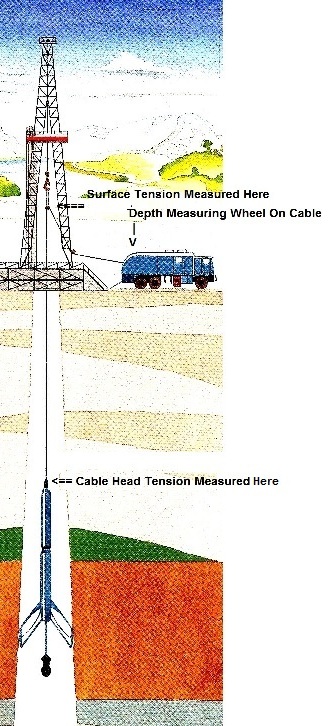
Key
elements of a wireline logging operation 
Accurate depth measurement can only be provided while measuring out
of hole. Logging while running in hole is done often, “Down Log”,
but the depth measurement provided can be described as no better
than Indicated Depth as there is no certainty as to the tensional
behaviour of the wireline during the descent.
This correction is often applied by the service company at the time
of logging the well based on standard stretch charts for the cable
type. For older worn cables, this correction may be too small. The
correction may be based on an assumed cable tension even when
tension is measured.
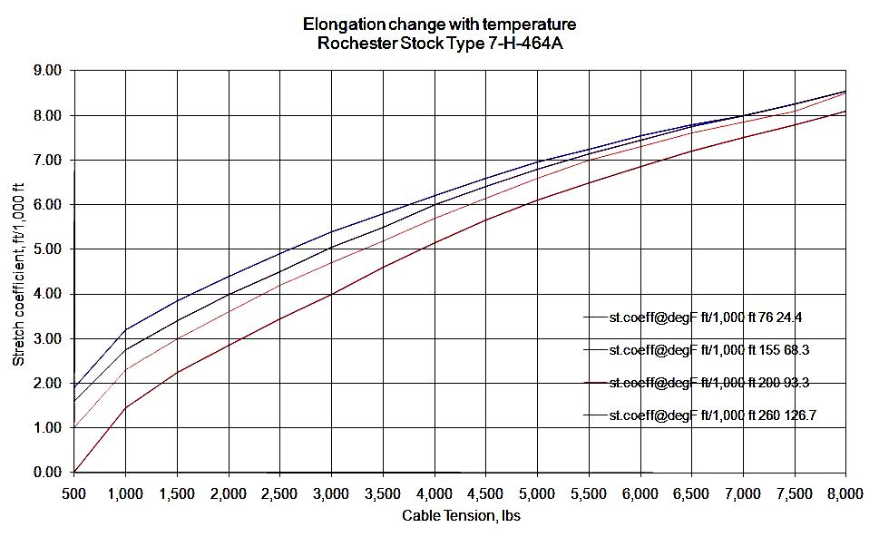
Due o friction between strands, multi-strand cables do not behave as
linear elastic wires, so the stretch coefficient KSTR varies with
applied tension and temperature, so these elements add a further
complication into the effective stretch coefficient that should be
used. It is clear that an accurate and verifiable measurement of
cable stretch coefficient is required to provide a credible
correction result.

Stretch coefficient behavior with temperature and line tension
 Tension Regimes
Over the length of a well, the characteristics of tension change
according to parameters such as deviation, well bore geometry, well
constructional characteristics, geology, rock properties, key
seating, tool configuration, etc., and these changes affect the
effective tension, and hence stretch, that the cable is subject to.
In our earlier discussion, it has been assumed that tension and
temperature are linear functions of depth and the corrections
therefore are a function of depth. This is not always the case,
especially for tension.
The measurement of surface and cable head tension over a logged
interval is referred to as a “Tension Regime”. A tension regime is
typically repeatable for the same logging string run in the same
well at the same time. This means that the tension regime can be
mapped, and then used to calculate the stretch correction to be used
in the depth interval defined by each tension regime. This level of
detail is NOT done by the service company at the time of logging the
well.

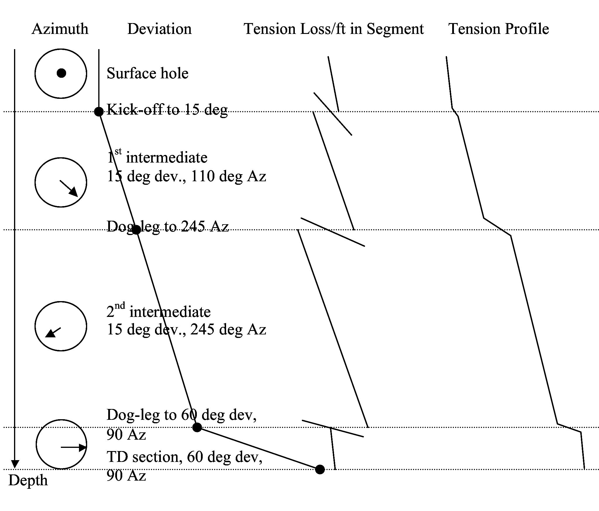
Tension regime elements combining Into tension profile
The contribution elements of the tension regime can be identified,
and built into so called “segments”, where each segment is
identified by a given loss of tension per length of well. These
stretch attributable to each individual segments then give rise to
the total stretch correction known as Segmented Correction. Equation
3 is then used in each segment with tension terms replaced with
tension at bottom of segment minus tension at top of segment, then
the segment contributions are summed together.
For the full story on this subject, contact haraldb@icteurope.com
|


