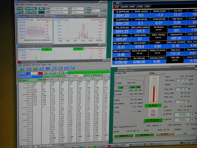
The real-time Measurement-While-Drilling (MWD)
screen showing a display of the pressure pulses sent
from the tools downhole (upper left), the data
transmission being decoded (lower left), as well as
a display of the drilling depth information (lower
right), and a display of the various parameters
(upper right).
The primary use of real-time surveys is in
directional drilling. For the directional driller to
steer the well towards a target zone, he must know
where the well is going, and what the effects of his
steering efforts are.
MWD tools can also provide information about the
conditions at the drill bit. This may include:
Rate of penetration
Rotational speed of the drill string
Smoothness of that rotation
Type and severity of any vibration downhole
Downhole temperature
Torque and weight on bit, measured near the drill bit
Mud flow volume
Use of this information can allow the operator to
drill the well more efficiently, and to ensure that
the MWD tool and any other downhole tools, such as
mud motors, rotary steerable systems, and LWD tools,
are operated within their technical specifications
to prevent tool failure.
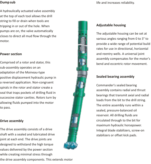
A typical MWD tool
string with steerable drilling motor.
 MWD / LWD TELEMETRY SYSTEMS
Mud pulse
telemetry is the most common method of data
transmission used by MWD tools. Downhole, a valve is
operated to restrict the flow of the drilling mud
according to the digital information to be
transmitted. This creates pressure fluctuations
representing the information. On surface, the
received pressure signals are processed by computers
to reconstructs the transmitted information. The
technology is available in three varieties -
positive pulse, negative pulse, and continuous wave.
Positive pulse tools briefly close and open the
valve to restrict the mud flow within the drill
pipe. This produces an increase in pressure that can
be seen at surface. Negative pulse tools briefly
open and close the valve to release mud from inside
the drill pipe out to the annulus. This produces a
decrease in pressure that can be seen at surface.
Continuous wave tools gradually close and open the
valve to generate sinusoidal pressure fluctuations
within the drilling fluid. Any digital modulation
scheme with a continuous phase can be used to impose
the information on a carrier signal. The most widely
used modulation scheme is continuous phase
modulation.
When under-balanced drilling is used, mud pulse
telemetry is unusable because a compressible gas is
injected into the mud. This causes high signal
attenuation which drastically reduces the ability of
the mud to transmit pulsed data. In this case, it is
necessary to use electromagnetic waves propagating
through the formation or wired drill pipe telemetry.
 Current
mud pulse telemetry technology offers a bandwidths
of up to 40 bits per second. The data rate drops
with increasing length of the wellbore and is
typically as low as 1.5 bps at a depth of 35,000 ft.
Data compression is used to increase the effective
data rate.
Current
mud pulse telemetry technology offers a bandwidths
of up to 40 bits per second. The data rate drops
with increasing length of the wellbore and is
typically as low as 1.5 bps at a depth of 35,000 ft.
Data compression is used to increase the effective
data rate.
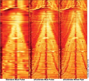
Borehole image log at
three different data
rates: standard mud pulse, accelerated mud
pulse, and wired pipe (left to right) 
Electromagnetic telemetry incorporate an electrical
insulator in the drill string. To transmit data the
tool generates an altered voltage difference between
the top part (the main drill string, above the
insulator), and the bottom part (the drill bit, and
other tools located below the insulator). On surface
a wire is attached to the wellhead, which makes
contact with the drill pipe. A second wire is
attached to a rod driven into the ground some
distance away. The wellhead and the ground rod form
the two electrodes of a dipole antenna. The voltage
difference between the two electrodes is the
received signal that is decoded by a computer.
This system generally offers data rates of up to 10
bits per second. In addition, many of these tools
are also capable of receiving data from the surface
in the same way, while mud pulse-based tools rely on
changes in the drilling parameters, such as rotation
speed of the drill string or the mud flow rate, to
send information from the surface to downhole tools.
Making changes to the drilling parameters in order
to send information to the tools generally
interrupts the drilling process, causing lost time.
Wired drill pipe systems use electrical wires built
into every component of the drill string, which
carry electrical signals directly to the surface.
These systems promise data transmission rates orders
of magnitude greater then anything possible with mud
pulse or electromagnetic telemetry, both from the
downhole tool to the surface, and from the surface
to the downhole tool, at data rates upwards of 1
megabit per second,
Retrievable tools, sometimes known as slim tools,
can be retrieved and replaced using wireline through
the drill string. This generally allows the tool to
be replaced much faster in case of failure, and it
allows the tool to be recovered if the drill string
becomes stuck. Retrievable tools must be much
smaller, usually about 2 inches or less in diameter,
though their length may be 20 feet or more. The
small size is necessary for the tool to fit through
the drill string, however, it also limits the tool's
capabilities. For example, slim tools are not
capable of sending data at the same rates as collar
mounted tools, and they are also more limited in
their ability to communicate with and supply
electrical power to other LWD tools.
Collar-mounted tools, also known as fat tools,
cannot generally be removed from their drill collar
at the well site. If the tool fails, the entire
drill string must be pulled out of the hole to
replace it. However, without the need to fit through
the drill string, the tool can be larger and more
capable.
GEOSTEERING WITH MWD DATA
In the process of drilling a borehole, geosteering
is the act of adjusting the borehole trajectory
(inclination and azimuth angles) as the well is
being drilled, so as to reach one or more geological
targets. These changes are based on geological and
position gathered from measurement while drilling
(MWD) techniques.
Models of underground
geological structures are made from available
geological data to plan a well trajectory. A well
plan is a continuous succession of straight and
curved lines representing the geometrical figure of
the expected well path. A well plan is projected on
vertical and horizontal maps.
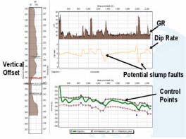
While the borehole is being drilled according to the
well plan, new geological information is gathered
from MWD or LWD measurements. These usually show
some differences from what was expected from the
model. As the model is continuously updated with the
new geological information and the borehole
position, changes in the trajectory can be initiated
to reach the corrected geological targets.
Geosteering and reservoir description (reservoir
modeling) are intimately linked. There is no point
steering a wellbore if you don't know where to go.
The following examples are taken from a recent
technical presentation "Horizontal Well
Geo-Navigation: Planning, Monitoring and
Geosteering" by Rocky Mottahedeh, P.Eng. P.Geol.
This paper was presented at the Petroleum Society’s
6th Canadian International Petroleum Conference
(56th Annual Technical Meeting), Calgary, Alberta,
Canada, June 7 – 9, 2005. .
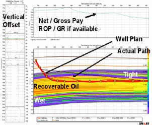
Well trajectory superimposed on a geostatistical
model of the reservoir (left) and MWD GR log and
well path (right) with FR log of vertical offset
well
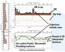
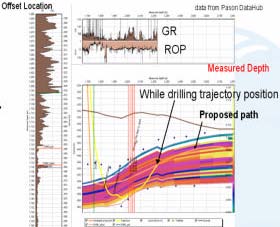
Illustration of steering back into sand after
entering shale (left) and actual versus proposed
trajectory imposed on reservoir model, GR and ROP
help confirm best sand quality (right).