|
 True
Vertical Depth
True
Vertical Depth
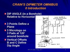
In
near-vertical wells, we can be reasonably sure of the depth
to a particular formation. In deviated wells, we need to
calculate true vertical depth to that formation AND place
the location where the wellbore intersects the reservoir.
The results of this calculation allow us to correctly
position reservoirs on geological sections, contour maps,
and 3-D visualizations.
True
vertical depth is a tricky business because six methods have been used
over the years. The results vary in accuracy depending on
how crooked the borehole is and how closely spaced the
survey points are positioned. For a relatively straight
deviated well, the tangential method is easy and quite
adequate. For a well with many twists and turns, and for
horizontal wells, more sophisticated methods are needed. The
minimum curvature method seems to be the most popular.
Directional surveys measure wellbore deviation from the
vertical and wellbore direction (azimuth) corrected to true
North. Typical directional surveys are run inside drill
pipe, with data measured every time a new drill pipe
stand is readied for use - this occurs every 100 feet (30
meters) give or take a bit. Older surveys mau have much
longer or erratic spacings between measurements.
With the increased use of horizontal wells in many
reservoirs, the accurate representation of the wellbore
trajectory between measurement stations has become
important, for both practical and legal reasons. The math
for this is a little beyond the scope of this Handbook.
Click
HERE for a description of a
Visual Basic assisted spreadsheet for this purpose. THIS CHAPTER
"A
Compendlum of Directional Calculations Based on the Minimum
Curvature Method", S.J. Sawaryn and I. L. Thorogood, SPE
84246, 2003.
Real-time continuous logging while drilling directional
surveys minimize the calculation problem while geo-steering
directional or horizontal wells. Continuous directional data
from dipmeters, image logs, and other open hole well logs
also give accurate results, but of course are "after the
fact" and cannot help with geo-steering. A virtue of well
logging methods is the ability to log data inbound and
outbound, making for a "closed" survey in which accumulated
closure errors can be distributed around the entire data
set. This cannot be done in conventional station by station
surveys.
CAUTION: If you write your own spreadsheets to run these
calculations, note that the default units for angles is
RADIANS and not degrees. The math below assumes angles are
in degrees except where noted in Method 6.
Tangential Method
The tangential method uses only the inclination and direction
angles measured at the lower end of the survey course length.
The well bore path is assumed to be a straight line throughout
the course. This method has probably been used more than any other
and is the least accurate. It makes the well appear too shallow
and the lateral displacement too large. In a typical deviated
well, the true vertical depth can be wrong by more than 50 feet.
It
has been used and perpetuated because of its inherent simplicity
of hand calculation. Calculating the survey by the tangential
method, however, is no longer justifiable because programmable
calculators and field portable computers make the better methods
just as easy as this one. This method is not recommended any time
in any well. However, many such surveys are in the well files
and many true vertical depths have been used, and may still be
accepted, based on this erroneous data. All that is needed for
a re-computation using better methods is the raw inclination and
direction data, and this is usually available. Re-computation
is strongly recommended.
If
surveys were taken at approximately 1 ft. intervals, the error
would be tolerable, but this frequency cannot be economically
justified with typical single shot surveys. However, this frequency
of measurement is achieved with continuous directional surveys
run with the dipmeter. If computations are made at short intervals,
then the tangential method works fine. Most station by station
surveys are taken at much larger intervals, such as a few to several
hundred feet apart, and therefore the results are inaccurate.
If the dipmeter program calculates vertical depth at similar intervals,
it is also inadequate.
The
formula are:
1: North = SUM ((MD2 - MD1) * Sin WD2 * Cos HAZ2)
2: East = SUM ((MD2 - MD1) * Sin WD2 * Sin HAZ2)
3: TVD = SUM ((MD2 - MD1) * Cos WD2)
NOTE:
This is the high tangential method. If WD1 and HAZ1 replace WD2
and HAZ2, it is the low tangential method.
Where:
East = easterly displacement (feet or meters) - negative = West
HAZ1 = hole azimuth at top of course (degrees)
HAZ2 = hole azimuth at bottom of course (degrees)
MD1 = measured depth at top of course (feet or meters)
MD2 = measured depth at bottom of course (feet or meters)
North = northerly displacement (feet or meters) - negative = South
TVD = true vertical depth (feet or meters)
WD1 = well deviation at top of course (degrees)
WD2 = well deviation at bottom of course (degrees)
Average Tangential
Method
The angle averaging method uses the angles measured at both the
top and bottom of the course length in such a fashion that the
simple average of the two sets of measured angles is assumed to
be the inclination and the direction. The wellbore then is calculated
tangentially using these two average angles over the course length.
This method is a very simple, and more accurate, means of calculating
a wellbore survey.
1: North = SUM ((MD2 - MD1) * Sin ((WD2 + WD1) / 2) * Cos ((HAZ2
+ HAZ1) / 2))
2: East = SUM ((MD2 - MD1) * Sin ((WD2 + WD1) / 2) * Sin ((HAZ2
+ HAZ1) / 2))
3: TVD = SUM ((MD2 - MD1) * Cos ((WD2 + WD1) / 2))
Balanced Tangential Method
The balanced tangential method uses the inclination and direction
angles at the top and bottom of the course length to tangentially
balance the two sets of measured angles. This method combines
the trigonometric functions to provide the average inclination
and direction angles which are used in standard computational
procedures. The values of the inclination at WD2 and WD1 are combined
in the proper sine-cosine functions and averaged. This method
did not lend itself to hand calculations in the early days, but
modern programmable scientific calculators make the job easy.
This
technique provides a smoother curve which should more closely
approximate the actual wellbore between surveys. The longer the
distance between survey stations, the greater the possibility
of error. The formula are:
1: North = SUM (MD2 - MD1) * ((Sin WD1 * Cos HAZ1 + Sin WD2 *
Cos HAZ2) / 2)
2: East = SUM (MD2 - MD1) * ((Sin WD1 * Sin HAZ1 + Sin WD2 * Sin
HAZ2) / 2)
3: TVD = SUM ((MD2 - MD1) * (Cos WD2 + Cos WD1) / 2)
Mercury Method
The mercury method is a combination of the tangential and the
balanced tangential method that treats that portion of the measured
course defined by the length of the measuring tool in a straight
line (tangentially) and the remainder of the measured course in
a balanced tangential manner. The name of the mercury method originated
from its common usage at the Mercury, Nevada test site by the
US Government.
1: North = SUM ((MD2 - MD1 - STL)*((Sin WD1 * Cos HAZ1 + Sin WD2
* Cos HAZ2)/2)
+ STL * Sin WD2 * Cos HAZ2)
2: East = SUM ((MD2 - MD1 - STL) * ((Sin WD1 * Sin HAZ1 + Sin
WD2 * Sin HAZ2) / 2)
+ STL * Sin WD2 * Sin HAZ2)
3: TVD = SUM (((MD2 - MD1 - STL) * (Cos WD2 + Cos WD1) / 2) +
STL * Cos HAZ2)
Where:
STL is the length of the survey tool
Radius of Curvature Method
The radius of curvature method uses sets of angles measured at
the top and bottom of the course length to generate a space curve
(representing the wellbore path) that has the shape of a spherical
arc passing through the measured angles at both the upper and
lower ends of the measured course. This method is one of the more
accurate means of determining the position of a wellbore when
survey spacing is sparse. The assumption that the wellbore is
a smooth curve between surveys makes this method less sensitive
to placement and distances between the survey points than other
methods.
CAUTION:
It is a terrible method when data is closely spaced, as the subtractions
in the equation create either "divide by zero errors"
or an incorrect TVD when the borehole is a straight line but deviated.
1: North = SUM (MD2 - MD1) * (Cos WD1 - Cos WD2) * (Sin HAZ2 -
Sin HAZ1)
/ ((WD2 - WD1) * (HAZ2 - HAZ1))
2: East = SUM (MD2 - MD1) * (Cos WD1 - Cos WD2) * (Cos HAZ1 -
Cos HAZ2)
/ ((WD2 - WD1) * (HAZ2 - HAZ1)}
3: TVD = SUM (MD2 - MD1) * (Sin WD2 - Sin WD1) / (WD2 - WD1)
Minimum Curvature Method
The minimum curvature method, like the radius of curvature method,
takes the space vectors defined by inclination and direction measurements
and smoothes these onto the wellbore curve by the use of a ratio
factor which is defined by the curvature (dog-leg) of the wellbore
section. The method produces a circular arc as does the radius
of the curvature. This is not, however, an assumption of the method,
but a result of minimizing the total curvature within the physical
constraints on a section of wellbore.
1: DL = Arccos (Cos (WD2 - WD1) - Sin WD1 * Sin WD2 * (1 - Cos
(HAZ2 - HAZ1)))
2: CF = 2 / DL * (Tan (DL / 2)) * 0.017 453
3: North = SUM ((MD2 - MD1)*((Sin WD1 * Cos HAZ1 + Sin WD2 * Cos
HAZ2) / 2) * CF)
4: East = SUM ((MD2 - MD1) * ((Sin WD1 * Sin HAZ1 + Sin WD2 *
Sin HAZ2) / 2) * CF)
5: TVD = SUM (((MD2 - MD1) * (Cos WD2 + Cos WD1) / 2) * CF)
Where:
DL = dog leg severity (degrees)
CF = curvature factor (radians)
The term 0.017 453
converts
degrees to radians.
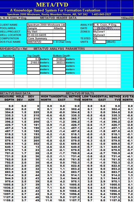
META/LOG
"TVD" SPREADSHEET -- True Vertical
Depth
This spreadsheet calculates True Vertical Depth
from seven common methods. The more exotic methods are more accurate
and there is no excuse for not using them, since the spreadsheet
does all the hard work.
SPR-23 META/LOG TRUE VERTICAL DEPTH (TVD) CALCULATOR
Calculate true vertical depth TVD, X aand Y coordinates,
7 methods.
///////
//////
///////
//////
/////// //////
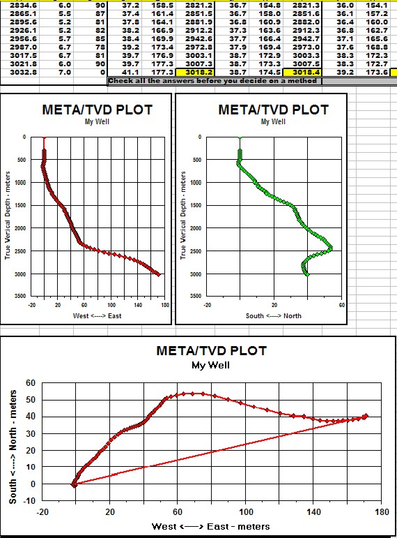
Sample output from META/LOG "TVD" Spreadsheet -several more sets of
results are offscreen to the right.
|