This page is a highly abbreviated version of Chapter 12 on this
website. For more about effextive porosity, alternate methods and examples, go
to the Main Index Page.
Logs read total porosity. All our analysis methods correct for shale, so the answers from any method presented below will give effective porosity. Some analysis methods NEED total porosity as an intermediate step, so you may also need to calculate it.
Raw log porosity, as presented in the field by the service company, does NOT take into account shale or lithology effects, so raw log readings should NEVER be used as answers. Log analysis MUST ALWAYS be done to find the correct porosity. All our analysis methods also account for matrix rock (lithology), but YOU may be required to define the rock type for some methods. Other methods will define the lithology for you.
YOU MUST choose a method that is appropriate for the available data and for the rock type being analyzed. The easiest methods are:
In all cases, the results must be trimmed to prevent too high a porosity in shaly zones and in bad hole by using Section 5.07: Material Balance for Porosity (Maximum Porosity). The META/ESP spreadsheet, available on the Downloads tab at www.spec2000.net, handles these models and makes the work relatively painless.
Unfortunately, there is no standard logging
program, so there is no single foolproof log analysis method.
Each method has its own usage rules. These rules may need to be
adjusted to suit local conditions. In the classroom or when
starting work in a new area, you may want to try several
methods, and see which matches core porosity the best.
The best method available for modern, simple, log analysis involves the density neutron crossplot. Several variations on the theme are common, but not all models are recommended. A crossplot method, called the shaly sand model was once widely used. It was found to be a poor model for any sandstone that contained other minerals in addition to quartz. The complex lithology model works equally well in quartz sands as in mixtures, so it is the preferred model today. Although the name of the method is complicated, the mathematics are not.
STEP 1: Shale correct the density and neutron log data for each layer: 1: PHIdc = PHID – (Vsh * PHIDSH) 2: PHInc = PHIN – (Vsh * PHINSH)
PHIDSH and PHINSH are constants for each zone, and are picked only once.
STEP 2: Check for gas crossover after shale corrections and calculate porosity for each layer from the correct equation: 3: IF PHInc >= PHIdc, there is no gas crossover 4: THEN PHIxdn = (PHInc + PHIdc) / 2
The density neutron crossplot porosity, PHIxdn, after all corrections are applied, is called the effective porosity, PHIe.
Density Neutron Complex Lithology Crossplot - Oil and Water cases, or Gas zones with crossover.
Chartbook solutions are provided above. Shale corrected data must be entered.
CASE 1: IF gas is known to be present AND gas crossover occurs after shale corrections, apply the following gas correction: 6: IF PHInc < PHIdc, there is gas crossover 7: THEN PHIxdn = ((PHInc ^ 2 + PHIdc ^ 2) / 2) ^ 0.5
CASE 2: IF gas is known to be present but no crossover occurs after shale corrections, this usually means gas in dolomite or in a sandstone with lots of heavy minerals, apply the following gas correction: 8: PHIx = – PHIdc / (PHInc / 0.8 – 1) / (1 + PHIdc / (0.8 – PHInc)) 9: PHIxdn = PHIx + KD3 * (0.30 – PHIx) * (DENSMA / KD1 – KD2)
Where: KD1 = 1.00 for English units KD1 = 1000 for Metric units KD2 = 2.65 for Sandstone scale log KD2 = 2.71 for Limestone scale log KD3 = 1.80 for Sandstone scale log KD3 = 2.00 for Limestone scale log
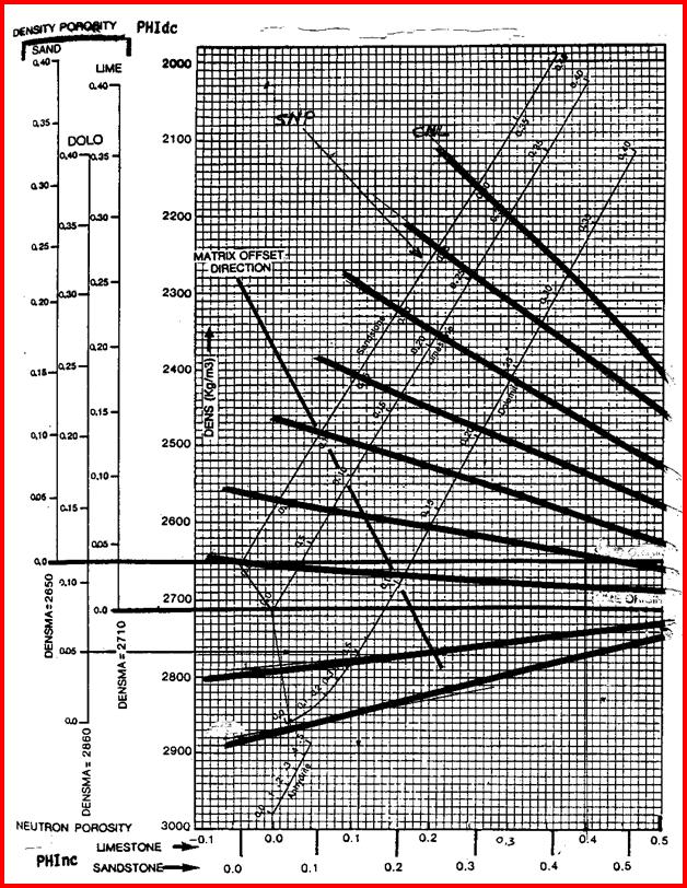
Density Neutron Complex Lithology Crossplot - Gas zones with NO crossover. Enter shale corrected data and then slide data point to the right until it reaches the line representing the matrix density of the reservoir - travel parallel to the nearest heavy black line.
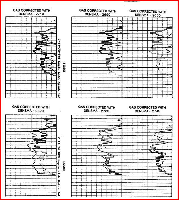
Do not use Dolomite scale log for this special case. Figure PP5.14 shows the effect of using this gas correction. Notice that computed porosity does not match core porosity unless the correct DENSMA is chosen. DENSMA should reflect the matrix density of the expected lithology. This can be predicted accurately if the PE curve can be used to determine mineral volumes in a two mineral model. Density and neutron data cannot be used for this purpose because the gas effect masks the mineral effect.
Chartbook solutions are provided below when gas is present. Shale corrected data must be entered.
CASE 3: IF rock is dolomite AND porosity is less than 5%, use the following instead of Equation 4 or 5: 10: E = (4 - (3.3 + 10 ^ (-5 * PHInc - 0.16)) 11: PHIxdn = (E * PHIdc + 0.754 * PHInc) / (E + 0.754)
This option can be used instead of equation 4 as long as there is no gas crossover after shale corrections. It is slightly more accurate, but requires a computer or preprogrammed calculator.
CASE 4: IF Archie or dual water model is to be used for water saturation, the following is needed: 12: BVWSH = (PHIDSH + PHINSH) / 2 (a constant for the zone) 13: PHIt = (PHID + PHIN) / 2 (one value for each layer)
CASE 5: IF zone is vuggy carbonate, calculate secondary porosity: 14: PHIsec = PHIxdn - PHIsc
· Do not use when density is affected by bad hole conditions.
· No correction for log units (eg Sandstone or Limestone units) is needed for most cases, except gas in dolomite and low porosity dolomite. Use Limestone units log ONLY for these two special cases.
· Answer porosity is accurate to +/- 1% porosity using the simplified rules.
· For better accuracy, use Equations 10 and 11 with Limestone units logs instead of simpler rules, except gas rules must still be applied.
· The matrix density required for the gas correction must be assumed from the sample descriptions or by calculating the lithology from the PE (photoelectric effect) log if it is available.
· Shale corrections could create apparent gas crossover and this may be real or an artifact of excessive correction. Check against known data from the well if shale correction creates crossover.
· Charts and math for sonic density and sonic neutron crossplots are provided in Chapter Seven of Crain’s Petrophysical Handbook.
· To calibrate to core porosity, adjust DENSMA, PHIDSH, PHINSH or Vsh to obtain a better match by trial and error. Appropriate crossplots may assist, or regression of PHIxdn vs core porosity may be used.
PHIDSH -0.06 - 0.15 (choose from log) PHINSH 0.15 - 0.45 (choose from log)
See Section 5.02 for matrix density (DENSMA) if needed for gas correction.
Effect of
DENSMA on density neutron crossplot porosity with gas in heavy
minerals. Core porosity (square black lines) and log analysis
porosity (smooth black curves) show a good match when DENSMA was
set at
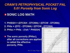
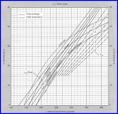
The sonic is a simple method and must be employed if more modern density neutron data is not available. The method shown is called the Wyllie time average equation. Other porosity methods are presented in following sections.
Other methods for the sonic have been proposed, but they are really specific to certain areas, although this is not clearly stated in the literature. For example, the Hunt-Raymer transform is appropriate for the US Gulf Coast, but a poor model for the Lower Cretaceous in Western Canada. The Wyllie approach, when calibrated to core, is universally applicable.
STEP 1: Calculate shale porosity (PHISSH), a constant for each zone: 1: PHISSH = (DTCSH – DTCMA) / (DTCW – DTCMA)
DTCSH is a constant for the zone, chosen from the sonic log in a nearby shale.
STEP 2: Calculate porosity from sonic log (PHIsc) for each layer in the zone: 2: PHIs = (DTC – DTCMA) / (DTCW – DTCMA) 3: PHIsc = PHIs – (Vsh * PHISSH)
The sonic porosity (PHIsc), after all corrections are applied, is called the effective porosity, PHIe.
CASE 1: Correct each layer for lack of compaction, ONLY IF DTCSH > 328 (Metric) or DTCSH > 100 (English) 4: PHIe = PHIsc / KCP
CASE 2: Correct each layer for gas effect, ONLY IF PHIsc > PHItrue and gas is known or suspected 5: PHIe = PHIsc * KS
· Use when density log is unavailable, or when density log is affected by bad hole.
· Of the three "one-log" porosity methods, the sonic corrected for shale is the preferred one for wells that have no density log. However, crossplot methods or the density log corrected for shale are usually better if the log data is available.
· If lithology is unknown, sonic log corrected for shale is better than density log because the lithology effect on the sonic is smaller.
· Use the compaction correction KCP only if DTCSH > 100 usec/ft (for English units) or DTCSH > 328 usec/m (for Metric units). In western North America, this is normally required when above 3,000 - 4,000 feet (900 – l,200 meters).
8: KCP = DTCSH / 100 (for English units) OR 9: KCP = DTCSH / 328 (for Metric units)
· KCP is never less than 1.0.
· Use the gas correction KS only if PHIsc is too high compared to other sources and if gas is known to be present. The need for this correction is common, but it is unlikely that a gas correction will be needed in very shaly sands since invasion should be relatively deep.
10: KS = PHItrue / PHIsc
· KS is never greater than 1.0.
· Another way of making gas corrections is to change DTCW to a higher value, representing the travel time of sound in a mixture of gas and water. This value depends on water saturation in the invaded zone, pressure, temperature, and gas compressibility. Values in the range of 600 usec/ft (1900 usec/m) at shallow depths to 300 usec/ft (950 usec/m) at 6000 feet (2000 meters) are recommended as a starting point.
· To calibrate to core porosity, adjust DTCMA, DTCW, DTCSH, KCP, KS, or Vsh to obtain a better match by trial and error. Appropriate crossplots may assist.
· A newer method called the Hunt - Raymer equation has been proposed, but it seems to work well only in the Gulf Coast of USA. Shale corrected data should be entered to this equation (not mentioned in original paper).
* English Metric usec/ft usec/m
DTCSH 60 - 150 190 – 480 (choose from log) KCP 1.0 - 1.4 1.0 - 1.4 KS 0.7 - 1.0 0.7 - 1.0
DTCW Fresh drilling mud 200 656 Salty drilling mud 188 616
Clean Quartz 55.5 182 Calcite 47.3 155 Dolomite 44.0 144 Anhydrite 50.0 164 Gypsum 52.4 172 Mica Muscovite 47.3 155 Biotite 55.5 182 Clay Kaolinite 64.3 211 Glauconite 55.5 182 Illite 64.6 212 Chlorite 64.6 212 Montmorillonite 64.6 212 Barite 69.8 229 NaFeld Albite 47.3 155 Anorthite 45.1 148 K-Feld Orthoclase 68.9 226sands Iron Siderite 44.0 144 Ankerite 45.7 150 Pyrite 39.6 130 Evaps Fluorite 45.7 150 Halite 67.0 220 Sylvite 73.8 242 DON'T use this graph in shaly sands !!!! Carnalite 78.0 256 Coal Anthracite 105 345 Lignite 160 525
For mixtures, take the average of two pure values as a starting point, eg: dolomitic sand, DTCMA = (144 + 182) / 2 = 163 usec/m, or prorate the values in proportion to the described mineral assemblage.
Another "one-log" method uses the density log data, and is favored in shaly sands because the shale correction is quite small. In carbonates, the rock composition must be known accurately. This method is better than the sonic log, provided lithology is well known and the density log is not affected by bad hole. The density neutron combination is better than either sonic or density alone. Many people read the density log porosity directly from the log and call it effective porosity, PHIe. This is NOT a good idea, as you could be wrong by as much as 12 percent porosity in the worst case, and a few percent in most cases.
STEP 1: Calculate shale density (DENSSH) from shale porosity (a constant for each zone): 1: DENSSH = PHIDSH * KD1 + (1 – PHIDSH) * KD2
PHIDSH is a constant for the zone, chosen from the density log in a nearby shale.
STEP 2: Translate density porosity of each layer into density units: 2: DENS = PHID * KD1 + (1 – PHID) * KD2
Where: KD1 = 1.00 for English units KD1 = 1000 for Metric units KD2 = 2.65 for English units Sandstone scale log KD2 = 2650 for Metric units Sandstone scale log KD2 = 2.71 for English units Limestone scale log KD2 = 2710 for Metric units Limestone scale log KD2 = 2.87 for English units Dolomite scale log KD2 = 2870 for Metric units Dolomite scale log
STEP 3: Calculate porosity of each layer with matrix and fluid of your choice: 3: PHIDm = (DENS – DENSMA) / (DENSW – DENSMA) 4: PHIdc = PHIDm – (Vsh * PHIDSH)
The density porosity (PHIdc), after all corrections are applied, is called the effective porosity, PHIe.
CASE 1: Correct each layer for gas effect, ONLY IF PHIdc > PHItrue and gas is known or suspected 5: PHIe = PHIdc * KD
· Do not use in bad hole conditions.
· Use if neutron log is not available, otherwise use density neutron crossplot
· Use in preference to sonic in shaly sands if both logs are available.
· The density log corrected for shale AND lithology is a very good approximation to porosity, but the log was not common before 1965, so sonic or neutron methods may be necessary for wells drilled before that time.
· Use gas correction KD only if PHIdc is too high compared to other sources and if gas is known to be present.
6: KD = PHItrue / PHIdc
· KD is never greater than 1.0.
· Another way of making gas corrections is to change DENSW to a lower value, representing the density in a mixture of gas and water. This value depends on water saturation in the invaded zone, pressure, temperature, and gas density. Values in the range of 0.25 g/cc (250 kg/m3) at shallow depths to 0.70 g/cc (700 kg/m3) at 6000 feet (2000 meters) are recommended as a starting point.
· If density porosity data is in percent, rather than fractional, divide the data values by 100 before using them.
· No compaction correction is made to density log data.
· To calibrate to core porosity, adjust DENSMA, DENSW, DENSSH, KD, or Vsh to obtain a better match by trial and error. Appropriate crossplots may assist.
* gm/cc kg/m3
DENSSH
2.50 - 2.83
2500 – 2830
KD 0.25 - 0.70 0.25 - 0.70
DENSW Fresh drilling mud 1.00 1000 Salty drilling mud 1.10 1100
DENSMA Clean Quartz 2.65 2650 Calcite 2.71 2710 Dolomite 2.87 2870 Anhydrite 2.95 2950 Gypsum 2.35 2350 Mica Muscovite 2.83 2830 Biotite 3.20 3200 Clay Kaolinite 2.64 2640 Glauconite 2.83 2830 Illite 2.77 2770 Chlorite 2.87 2870 Montmorillonite 2.62 2620 Barite 4.08 4080 NaFeld Albite 2.58 2580 Anorthite 2.74 2740 K-Feld Orthoclase 2.54 2540 Iron Siderite 3.91 3910 Ankerite 3.08 3080 Pyrite 5.00 5000 Evaps Fluorite 3.12 3120 Halite 2.03 2030 Sylvite 1.86 1860 Carnalite 1.56 1560 Coal Anthracite 1.47 1470 Lignite 1.19 1190
For mixtures, take the average of two pure values as a starting point, eg: dolomitic sand, DENSMA = (2870 + 2650) / 2 = 2760 kg/m3 or prorate in proportion to mineral volumes.
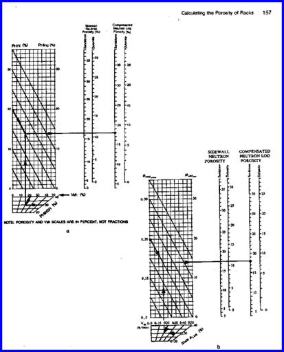
The third, and least accurate, "one-log" method is based on neutron log data. The method is used in old wells or cased holes where no other porosity data is available, or where the sonic log was not run and the density log suffers from bad hole conditions.
STEP 1: Adjust log values from each layer to correct for matrix rock: 1: PHINm = (PHIN – PHINMA + KN1) / (PHINW – PHINMA)
Where: KN1 = 0.028 for Sandstone units log KN1 = 0.000 for Limestone units log KN1 = -0.100 for Dolomite units log
This lithology approximation is not sufficient in low porosity and service company chartbooks should be used for the specific tool.
STEP 2: Apply shale corrections to each layer: 2: PHInc = PHINm – (Vsh * PHINSH)
PHINSH is a constant for each zone, chosen from the neutron log in a nearby shale.
The neutron porosity (PHInc), after all corrections are applied, is called the effective porosity, PHIe.
CASE 1: Old style GRN or unscaled neutron logs recorded in counts per second or API units 1: SLOPE = (log (PHIHI / PHILO)) / (CPSHI – CPSLO) 2: INTCPT = PHIHI / (10 ^ (CPSHI * SLOPE)) 3: PHIn = INTCPT * (10 ^ (SLOPE * NCPS)) 4: PHInc = PHIn – Vsh * PHINSH
Example of Porosity from Neutron Counts per Second - no shale correction
A large number of charts for specific tools, spacings, borehole conditions and rock types are available from service companies.
CASE 2: Apply gas correction to each layer, ONLY IF PHInc < PHItrue and gas is known or suspected 1: PHIe = PHInc * KN
· Use only if sonic and density log are unavailable or unusable.
· The neutron log corrected for shale is one of the least accurate methods in shaly sands and should only be used if no other porosity data is available. This is common for wells drilled prior to 1957 or for wells logged through casing or drill pipe.
· Old style neutron logs recorded in counts per second need to be scaled logarithmically between a high and a low porosity point, calibrated by core or modern logs from offset wells.
· Use the gas correction KN only if gas is known to be present and log reading is still too low after lithology corrections. This correction is very crude and not recommended. KN = PHItrue / PHIN
· KN is never less than 1.0, range is 1.0 to 3.0.
· To calibrate to core porosity, adjust PHINMA, PHINW, PHINSH, KN, or Vsh to obtain a better match by trial and error. Appropriate crossplots may assist.
PHINSH 0.15 - 0.45 (choose from log)
PHINW Fresh drilling mud 1.00 Salty drilling mud 1.00
PHINMA Clean Quartz - 0.028 Calcite 0.000 Dolomite PHIe = 5.5 - 30% 0.100 PHIe = 1.5 - 5.5% 0.050 PHIe = 0 - 1.5% 0.005 Anhydrite 0.002 Gypsum 0.507 Mica Muscovite 0.165 Biotite 0.225 Clay Kaolinite 0.491 Glauconite 0.175 Illite 0.158 Chlorite 0.428 Montmorillonite 0.115 Barite 0.002 NaFeld Albite - 0.013 Anorthite 0.018 K-Feld Orthoclase 0.011 Iron Siderite 0.129 Ankerite 0.057 Pyrite - 0.019 Evaps Fluorite - 0.006 Halite - 0.018 Sylvite 0.041
Carnalite
0.584 Lignite 0.542
Another version of the density neutron crossplot is the dual water, or bulk volume water method. This form should be used only in shaly sands with no heavy minerals. The simplified equations (5a and 6a) account for heavy minerals and are recommended over the original, more complex formulation which was meant for quartz sands ONLY.
For people who prefer chartbook solutions instead of calculators, a graph must be made manually for each zone to be analyzed. This is not recommended, so dig out the calculator and get at it.
STEP 1: Adjust log values for each layer to correct units. If in limestone units, put logs into sandstone units: 1: PHID = PHID – 0.03 2: PHIN = PHIN + 0.04
STEP 2: Calculate neutron dry clay (PHINDC) from PHIDDC, and shale bound water (BVWSH), which are constants for the zone 3: PHIDDC = (DENSDC – KD2) / (KD1 – KD2)
Where: KD1 = 1.00 for English units KD1 = 1000 for Metric units KD2 = 2.65 for English units Sandstone scale log KD2 = 2650 for Metric units Sandstone scale log
4: PHINDC = 1.00 - (1.00 - PHIDDC) * (1.00 - PHINSH) / (1.00 - PHIDSH) 5: BVWSH = (PHINDC * PHIDSH - PHIDDC * PHINSH) / (PHINDC - PHIDDC)
These are constants for each zone. PHIDDC is usually negative, so watch the minus sign when using the above equations.
STEP 3: Calculate total porosity for each layer: 6: PHIt = (PHINDC * PHID – PHIDDC * PHIN) / (PHINDC – PHIDDC)
An easier approximation is: 5a: BVWSH = (PHIDSH + PHINSH) / 2 (a constant for the zone) 6a: PHIt = (PHID + PHIN) / 2 (one value for each layer)
STEP 4: Calculate effective porosity in each layer: 7: PHIbvw = PHIt – (Vsh * BVWSH)
If matrix offset is required for heavy minerals, apply the offset to all neutron and density values including shale points, then use the above equation.
Nothing special is done in gas zones, as the values computed for PHIt and PHIe are reasonable even if gas crossover occurs. If this rule seems uncomfortable use: 8: PHIbvw = ((PHInc ^ 2 + PHIdc ^ 2) / 2) ^ 0.5
The dual water density neutron crossplot porosity PHIbvw, after all corrections are applied, is called the effective porosity, PHIe.
· Use in shaly sands without heavy minerals. If heavy minerals are present, the complex lithology density neutron crossplot is preferred.
· The method is also called the bulk volume water (BVW) method and is the basis of many wellsite and office computer programs.
· If the simplified equations 5a and 6a are used, the results are numerically identical to the Complex Lithology Model, except that no special cases are covered.
· To calibrate to core porosity, adjust DENSDC, PHIDSH, PHINSH or Vsh to obtain a better match by trial and error. Appropriate crossplots may assist, or regression of PHIbvw vs core porosity may be used.
* English Metric * gm/cc kg/m3 DENSDC Mica Muscovite 2.83 2830 Biotite 3.20 3200 Clay Kaolinite 2.64 2640 Glauconite 2.83 2830 Illite 2.77 2770 Chlorite 2.87 2870 Montmorillonite 2.62 2620 Barite 4.08 4080
This method assumes that lithology is known from a UMA - DENSMA 3 mineral model or some other method that will determine mineral volumes accurately. The method can also be used if V1 and V2 (and V3 if desired) are derived from sonic density neutron (Mlith/Nlith or DTCMA/DENSMA), core description, or sample description.
STEP 1: Calculate shale density from shale porosity (a constant for each zone): 1: DENSSH = PHIDSH * KD1 + (1 – PHIDSH) * KD2
PHIDSH and DENSSH are constants for each zone, chosen from the density log in a nearby shale.
STEP 2: Translate density porosity for each layer to density units: 2: DENS = PHID * KD1 + (1 – PHID) * KD2
Where: KD1 = 1.00 for English units KD1 = 1000 for Metric units KD2 = 2.65 for English units Sandstone scale log KD2 = 2650 for Metric units Sandstone scale log KD2 = 2.71 for English units Limestone scale log KD2 = 2710 for Metric units Limestone scale log KD2 = 2.87 for English units Dolomite scale log KD2 = 2870 for Metric units Dolomite scale log
STEP 3: Calculate matrix density from lithology results: 3: DENSma = (Vmin1 * DENS1 + Vmin2 * DENS2 + (1 – Vmin1 – Vmin2) * DENS3) * (1 – Vsh) + Vsh * DENSSH
STEP 4: Calculate porosity from density response equation: 4: PHIped = (DENS – DENSma) / (DENSW – DENSma)
The photoelectric density neutron crossplot porosity, after all corrections are applied, is called the effective porosity, PHIe.
Cannot be used in gas zones or in bad hole.
· Use when data is available, but use care since errors in lithology calculation are exaggerated into the porosity equation.
· Do not use in bad hole conditions or in gas zones.
· This method is equivalent to a 4 mineral model where one mineral is considered to be porosity. Shale, which is calculated separately, is a fifth mineral.
· The model can be rephrased as a two mineral model by setting V3 to zero (ie V1 + V2 = 1.0.
· To calibrate to core porosity, adjust DENS1, DENS2, DENS3, DENSSH or Vsh to obtain a better match by trial and error. Appropriate crossplots may assist, or regression of PHIped vs core porosity may be used.
See Section 5.02 for matrix density (DENS1, 2, 3) values to represent minerals 1, 2, and 3.
Bad hole, high shale volume, and statistical variations can cause erratic results in both very low and high porosities. Values from any method used should be trimmed by the following: 1: IF PHIe < 0 2: THEN PHIe = 0 3: IF PHIe > PHIMAX * (1 - Vsh) 4: THEN PHImx = PHIMAX * (1 - Vsh) 5: AND PHIe = Min (PHIe, PHImx)
· Use always to trim excessive porosity due to wet shales or bad hole conditions.
· This material balance prevents the sum of shale volume, porosity, and rock matrix from exceeding 100%, and prevents porosity in the sand fraction of a shaly sand from reaching ridiculous values.
· It is also useful for estimating porosity in shaly sands where only an SP or gamma ray log is available. Bear in mind that this approach provides a porosity value based only upon the shale content and the analyst's assumed maximum possible porosity. With offset well data for control this is not a bad approach for wells with a very limited log suite. It is often used in computer analysis of ancient logs. Because of its gross assumptions, a warning note should be annotated on the results, if the method is used in this manner.
The figure below shows results from a number of different porosity techniques, all of which have been trimmed by PHIMAX. A spreadsheet called META/ESP is available on the Downloads tab at www.spec2000.net that makes the work relatively painless.
Comparison of results from various porosity methods. It is fairly easy to calibrate any method to match core porosity but more difficult to match perfectly in shaly sands.
There is a recent trend among petrophysicists and engineers to partition porosity into a useful and a non- useful fraction. The concept of useful porosity, as opposed to effective porosity, is helpful where very small pores exist. These tiny pores do not connect to other pores and thus do not contribute to useful reservoir volume or reservoir energy. They are invariably water filled and nothing flows from them or through them. The tiny pores are called micro porosity; the larger, more effective, pores are called macro porosity. Thus: 1: PHIuse = PHIe – PHImicro
In sandstones, micro porosity is often associated with volcanic rock fragments that are part of the sandstone mineral mixture. In carbonates, micro porosity is associated with micrite, matrix, or pin point vugs.
The quantity of micro porosity cannot always be found directly from logs but is usually assessed as a constant fraction, KM1, of the effective porosity. This constant can be found by examination of thin section visual porosity. Where micro porosity is associated with silt or a volcanic mineral (Vmin2) in a quartz sandstone: 2: KM1 = Vsilt / (Vqrtz + Vsilt) OR 2A: KM1 = Vmin2 / (Vqrtz + Vmin2) 3: PHIuse = PHIe * (1 – KM1)
In some cases, the micro porosity is assumed to be a constant, PHIoffset, over an interval (ie, PHImicro is not proportional to effective porosity). This appears to happen in carbonates with unconnected pin point vugs (PHIppv), micritic carbonates (PHImict), or carbonates with matrix porosity (PHImatr). In all three cases, PHIoffset is found by comparing visual porosity in thin sections to log analysis porosity. 4: PHIuse = PHIe - PHIoffset
In log analysis terminology, matrix porosity usually means effective porosity (PHIe). However, in petrographic (thin section) analysis, matrix porosity (PHImatr) is non-useful porosity contained in the very fine grained matrix material deposited between the granular or crystalline rock structure.
PHIppv, PHImict, and PHImatr may be varied according to rules developed by the analyst for the zone. A crossplot of visual porosity from thin section analysis versus PHIe from logs is a useful tool for determining the appropriate correction to obtain PHIuse. Typical rules might be: 5: PHIuse = PHIe – PHIsec (This is pretty pessimistic) 6: PHIuse = PHIsec (This may be optimistic) 7: PHIuse = PHIe – KMATR * (1 – PHIe) / (1 - KMATR) 8: PHIuse = PHIe – PHIsc * KMICT / PHISavg
KMATR and KMICT would be in the range 0.01 to 0.08, averaging 0.04, and cannot exceed PHIt.
The Log Response Equation for modern nuclear magnetic logs is the same as for all other logs. The difference between the NMR and other porosity logs is that the Log Response Equation is solved by the service company at logging time, instead of by the analyst after the logs are delivered. This transform is illustrated below.
The matrix and dry clay terms of NMR response are zero. An NMR log run today can display clay bound water (CBW), irreducible water (capillary bound water, BVI), and mobile fluids (hydrocarbon plus water, BVM), also called free fluids or free fluid index (FFI). On older logs, only free fluids (FFI) is recorded and some subtractions, based on other open hole logs, are required.
Nuclear Magnetic Resonance Response to Fluids For modern logs: 1: PHIt = CBW + BVI + BVM 2: PHIe = BVI + BVM
3: PHIuse = BVM
Some or all of the sums defined above may be displayed on the delivered log. Log presentation is far from standard for NMR logs. In some situations, mobile water can be separated from hydrocarbon, and sometimes gas can be distinguished from oil, by further (experimental) processing of the original signal. However, the depth of investigation and measurement volume are tiny, so the hydrocarbon indication is from the invaded zone.
For the same reason, PHIt and PHIe from NMR do not always agree with that derived from density neutron methods, which see much larger volumes of rock.
For older logs: 1: PHInmr = FFI 2: SWir = KBUCKL / PHInmr 3: PHIe = FFI / (1 – SWir) 4: BVWSH = (PHINSH + PHIDSH) / 2
5: PHIt = PHIe + Vsh * BVWSH
PHIe and PHIt should be compared to density neutron or other methods defined earlier.
KBUCKL is in the range 0.010 to 0.100, with a default of 0.040.
There are a number of techniques published for calculating fracture porosity from conventional open hole logs. All were developed before the processing of formation micro-scanner data for fracture aperture became common. These older methods over-estimate fracture porosity. The only correct method is to use fracture aperture and frequency data from FMI/FMS processed logs:
Where: KF1 = number of main fracture directions = 1 for sub-horizontal or sub-vertical = 2 for orthogonal sub-vertical = 3 for chaotic or brecciated PHIfrac = fracture porosity (fractional) Df = fracture frequency (fractures per meter) Wf = fracture aperture (millimeters)
Fracture porosity is exceedingly small and seldom is larger than 0.25% (0.0025 fractional). This is well below the noise level of conventional open hole logs. Fracture aperture from cores or thin section may be exaggerated due to stress release, so be cautious using this data. Some “fracture-related” porosity, such as solution porosity near the fracture face, will be seen by conventional logs, which is why some older fracture porosity methods give quite high values for fracture porosity.
There are a number of techniques for handling ancient logs like the old electrical survey (ES). The simplest is to use the shallow resistivity and assume that the flushed zone water saturation is near 1.0.
1: PHIxo = (A /
((RXO / RMF@FT) * (SXO ^ N))) ^ (l / M)
The microlog can also be used:
1: IF RES2 >
RES1
Mud
Weight
KML |
|
||
|
Page Views ---- Since 01 Jan 2015
Copyright 2023 by Accessible Petrophysics Ltd. CPH Logo, "CPH", "CPH Gold Member", "CPH Platinum Member", "Crain's Rules", "Meta/Log", "Computer-Ready-Math", "Petro/Fusion Scripts" are Trademarks of the Author |
|||

|
||
| Site Navigation | PETROPHYSICS COURSE HOW TO CALCULATE POROSITY | Quick Links |
 DTCMA
DTCMA *
English
Metric
*
English
Metric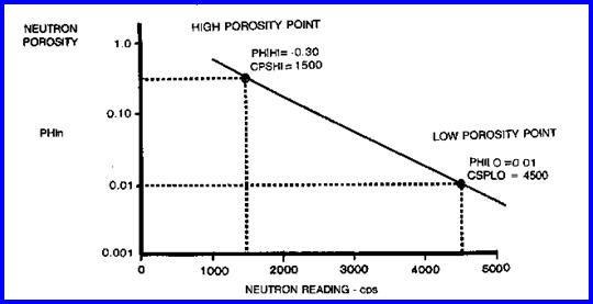
 KN
1.0 - 3.0
KN
1.0 - 3.0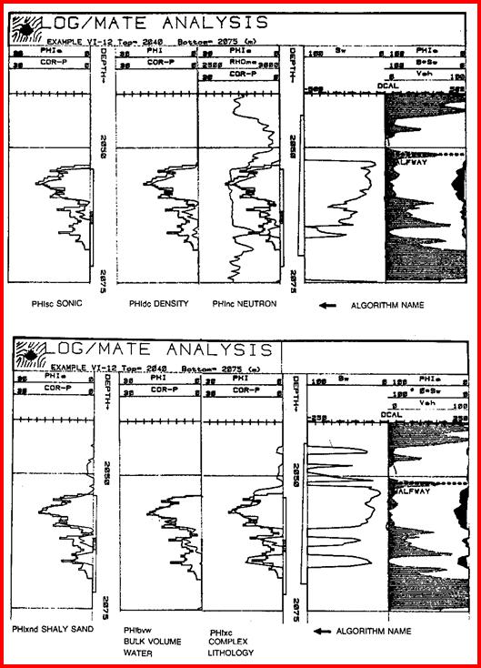
 1: PHIfrac = 0.001 * Wf * Df * KF1